Technical Manual for Corps Water Management Systems Model Development
Executive Summary
The Technical Manual (TM) for Corps Water Management System (CWMS) describes the Modeling, Mapping, and Consequences (MMC) Production Center’s purpose, requirements, products, and standards for CWMS implementation. This MMC technical manual describes the basic process and standard procedures used in the development and implementation of watershed modeling for CWMS. Supporting documentation includes the appendices detailing the technical aspects and background for the MMC CWMS staff. The CWMS program manager can answer specific standard operating procedure (SOP) questions and assist in locating supporting documentation. Additionally, the MMC Program Management Manual provides information about the MMC Production Center including scope, purpose, organization, duties, funding, schedules, and workflows.
CWMS is the automated information system used by the U.S. Army Corps of Engineers (USACE) to support its water control management mission. This mission encompasses the regulation of river flow through more than 700 reservoirs, locks, and other water control structures located throughout the nation. CWMS is an integrated system of hardware and software that begins with the receipt of hydrometorologic, watershed, and project status data. This data is then processed, stored, and viewed through a user-friendly interface which allows water managers to evaluate and model the watershed. CWMS allows for the evaluation of any number of operational alternatives before a final forecast scenario and release decision are adopted. The software also allows for the dissemination of these decisions to others within USACE and to the public.
Section 1 - Planning and Coordination
Planning and coordination efforts are critical to the success of the overall CWMS National Implementation Program. District involvement throughout the project’s duration is essential for the program’s success. During the planning and coordination phase, watersheds are selected and teams are formed. Initial data is gathered and the kickoff meeting is held to being the project.
1.1 Watershed Selection
Watershed selections are based on the funding program source each fiscal year (FY). CWMS watersheds are currently funded by Headquarters, U.S. Army Corps of Engineers (HQ USACE) and the CWMS advisory group (AG) determines watershed priorities for each division. These priorities are combined to form the group of watersheds to be modeled each FY. In the future, other funding sources or USACE program needs, such as planning studies, may influence the decision process and reprioritize watershed development efforts. Prior to the HQ funding source, CWMS was funded by the Risk Management Center (RMC) and watersheds were selected based on the RMC priorities, which included looking at Dam Safety Action Classification (DSAC) ratings of dams within the basin; the number (or percent) of DSAC 1, 2, and 3 dams in the watershed; the number of USACE levee systems in the watershed; and district priority for the watersheds.
1.2 Team Formation
CWMS teams are formed using experienced personnel from the district where the watershed is located. Should the district need additional support to staff the team, the MMC CWMS modeling branch chief will reach out to the division for support. Alternatively, other resources across USACE are available. If necessary, contract support may be used to complete the work. A sample team roster is shown in Figure 1-1.
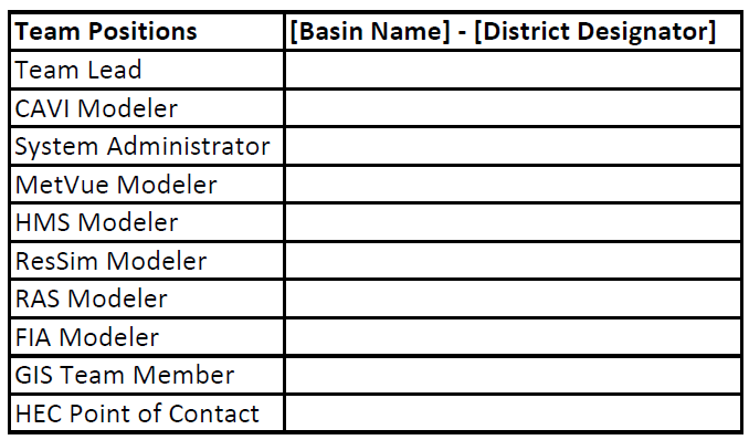
Figure 1-1. Sample Team Roster
1.3 Geographic Information System Data Call
The MMC mapping technical lead, in coordination with the CWMS mapping team, will contact the district to discuss the available data. Geographic Information System (GIS) data sets requested include:
- Digital elevation models (DEMs)
- Stream centerlines
- Watershed polygons
- Topographic data
- Aerial imagery
- Land use polygons or grids
- Soil data polygons or grids
- Gage locations
- Lake boundary polygons
- National Levee Database (NLD) layers
- Municipal, county, and state boundaries
- National Weather Service (NWS) forecast locations
- Impact area locations
- Political boundaries
1.4 Folder Structure
The standardized CWMS project folder structure is shown in Figure 1-2. After the GIS data call, the MMC CWMS mapping technical lead creates the watershed folder on the ProjectWise server. See Appendix 3.1.3 for additional information about storing files on ProjectWise.
1.5 Coordination Conference Call
Prior to the kickoff meeting at the district, the CWMS team lead and GIS team member should hold a conference call with the local water management chief or district point of contact (POC). All logistics should be finalized during this call, including the meeting room location and required attendees for the kickoff meeting. Data collection efforts are also discussed during this call. Sections 1.5.1–1.5.4 provide detailed information about data requirements. Collected data is uploaded to the appropriate folders in ProjectWise allowing all team members the opportunity to conduct a cursory review of the data prior to the kickoff meeting.
1.5.1 Real-time Gage Information
Establishing gage data and information availability is paramount prior to model development. The district’s list of gage information, including details regarding the acquisition of the data and its source, is provided to the team for review prior to the kickoff meeting.
1.5.2 Historic Model Data
Historic models for the Hydrologic Modeling System (HEC-HMS), the Reservoir System Simulation (HEC-ResSim), the River Analysis System (HEC-RAS), and the Flood Impact Analysis (HEC-FIA) are identified and provided by the district. Prior to the kickoff meeting, the CWMS modeling team reviews all existing models. The team should prepare to discuss the usability of each model and whether to incorporate it into the CWMS watershed models during the kickoff meeting.
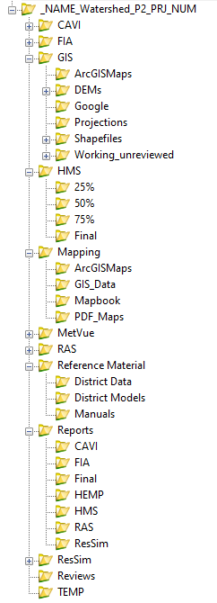
Figure 1-2. Example ProjectWise Folder Structure
1.5.3 Reference Material
Reference materials are provided by the district to the CWMS team lead prior to model development. Potential reference materials include:
- Water control manuals (WCMs)
- Design memorandums
- As-built drawings
- Operating plans
- Pool elevation-storage-area curves
- Release capacity curves
- Hydropower and generation capacity efficiency curves
- Tailwater rating curves
- Hydropower schedules and contracts
- Operating objectives and constraints
- Control points
- Lag times between gages
- Hydrology studies
- Issue Evaluation Studies (IESs), Periodic Assessments (PAs), Interim Risk Reduction Measures (IRRMs), Interim Operating Plans (IOPs), Dam Safety Modification Studies (DSMSs), or MMC studies.
1.5.4 Historic Storm Information
Historic storm information needed for calibration of the models is discussed during the coordination call. This information could include:
- Point gage rainfall data
- Gridded precipitation data
- High water marks and corresponding flow data
- Aerial flood imagery
- Period of record information for stream gages, precipitation gages, and lake gages
1.6 Kickoff Meeting
The kickoff meeting is held at the district prior to model development. The goals of the meeting are to familiarize the CWMS team members with the watershed, establish coordination between the CWMS team and the district, and ensure all stakeholders understand the goals and objectives of the project. The kickoff meeting is critical because it establishes the path forward for model development. During the kickoff meeting, a draft Hydrologic Engineering Management Plan (HEMP) is developed summarizing the outcomes from the meeting. Section 1.6.1 provides further details about the HEMP and Sections 1.6.2–1.6.9 outline topics for discussion during the kickoff meeting.
1.6.1 Draft Hydrologic Engineering Management Plan Formation
The HEMP is a project management plan developed in the planning stage of a watershed project and serves as an agreement between the MMC, the district, and HEC. The CWMS team lead is responsible for developing a draft HEMP during the kickoff meeting that summarizes all outcomes from the meeting. The HEMP contains site specifications and requirements, identifies project team members, and outlines the data required to successfully develop and calibrate the watershed models. The HEMP is a living document updated by the CWMS team lead throughout the project life cycle. A copy of the HEMP is uploaded to ProjectWise once approved and signed.
1.6.2 Water Management Operations
During the kickoff meeting, the district presents the various water management operations performed within the basin to the team. The operational plan for the watershed is discussed and documented in the draft HEMP. This discussion, along with all WCMs for structures within the basin, will provide the modelers with some of the necessary information to build the models.
1.6.3 Watershed Overview Diagram
The stream alignment is critical in the development of all watershed models. Stream alignment extents and watershed boundaries are agreed upon and finalized during the kickoff meeting. A watershed schematic is developed by the team in a stick figure or GIS map format to highlight the reservoirs, levees, diversions, locks and dams, gages, and critical flow/stage control points. Ultimately, the watershed schematic ensures the district and all CWMS modeling team members have input in the final stream alignment. The CWMS team lead works with CWMS GIS team members to ensure all NLD levees within the basin are identified and included within the agreed-upon stream alignment.
Within the watershed, the HEC-RAS and HEC-FIA models need to capture the extent of the probable maximum flood (PMF) dam failure flood to prevent unnecessary modifications by other MMC modelers in the future. All dam failure study or existing Emergency Action Plan (EAP) maps are reviewed and used to estimate the maximum model extents needed within the watershed. The MMC encourages teams to model HEC-RAS and HEC-FIA beyond the watershed boundaries, if needed, to capture PMF dam failure flood events.
1.6.4 Discussion of Collected Data
CWMS team members and district support staff discuss the collected GIS and Hydraulics and Hydrology (H&H) data as a group to validate usability, identify missing information, and determine a path forward. The following are the topics to be discussed:
- Real-time gage information
- Location of current gages
- Gage ownership
- Current CWMS database status
- Additional needs
- Existing model data
- Model extents
- Model parameters
- Horizontal projections
- Vertical datum
- Calibration events
- Bathymetric data sources
- Age of model/input data
- Reference Material
- Verify materials are current and meet the needs of modelers
- Historic Storm Information
- Calibration events
- Availability of data (precipitation grids, gage records, etc.)
- Antecedent conditions (wet versus dry)
- Regional climatology (rainfall/snowmelt).
All existing models used must comply with current MMC standards. Additionally, all data will remain on ProjectWise regardless of the decisions made during the meeting regarding usability.
1.6.5 Calibration Events
The team and district will select calibration storm events for the watershed and document them in the draft HEMP. It is recommended that the team select storm events occurring within the last 5–10 years, increasing the likelihood of obtaining required data for calibration and ensuring basin characteristics at the time the storms occurred are similar to existing conditions.
1.6.6 Model Interaction
The team identifies key locations in the watersheds where data is exchanged between the models, also known as common computation points (CCPs), to ensure each modeler understands the interaction between the different models. These decisions are documented in the draft HEMP.
1.6.7 Roles and Responsibilities
Detailed descriptions of the roles and responsibilities of each team member can be found in the MMC Program Management Manual. The CWMS team lead discusses the roles and responsibilities of each team member and the district. District involvement during the entire project is essential for success.
1.6.8 Project Schedule
The project schedule is discussed to ensure all parties involved in the modeling and review process understand the timeframes for milestone completion. The CWMS team lead may also discuss the setup of weekly/bi-weekly coordination meetings for the team. District involvement in these meetings is highly encouraged. The project schedule is documented in the draft HEMP.
1.6.9 Project Reviews
Project reviews are conducted at the end of each modeling milestone by a combination of MMC, HEC, and district personnel. During the kickoff meeting, the CWMS team lead discusses the availability of the district to provide support for these reviews. If the district cannot meet these needs, the MMC will assist in finding reviewers. The review process is detailed in Section 9.2 of this technical manual.
1.7 Pre-Modeling Watershed Coordination
Pre-modeling watershed coordination should begin soon after the kickoff meeting has ended, as explained in Sections 1.7.1–1.7.5.
1.7.1 Corps Water Management System User Account Setup
The CWMS system administrator at the district (or HEC) establishes user accounts for the team members and district staff after the kickoff meeting. The CWMS Administration Manual is used as a guide during this process.
1.7.2 Geographic Information System Pre-Model Deliverables
The following pre-model deliverables shall be provided by the mapping team in the MMC standard horizontal coordinate system and vertical datum:
- Study area
- DEM derived from the National Elevation Dataset (NED) 1/3 ArcSecond dataset
- Stream centerlines
- Gage locations
- Vertical datum conversion points (for stream centerlines)
- NLD datasets, such as levees and floodwalls
- Dam locations
- Cities and towns
- Soil data
- Land use data
- Hillshade rasters
- Light Detection and Ranging (LiDAR) data if available.
See the Pre-Modeling Data Production Guide (Appendix 4.1.1) for further instructions.
1.7.3 Development of the Stream Alignment
The preliminary stream alignment is developed using the National Hydrography Dataset (NHD) ( https://www.usgs.gov/core-science-systems/ngp/national-hydrography). The stream alignment should be discussed during the kickoff meeting. Following the meeting, the CWMS team lead and all modelers work with the GIS team member to develop the final stream alignment. The stream alignment is a critical component of the project and should be developed with consideration of all models to ensure consistency and suitability. It is the responsibility of all modelers to review and approve the final stream alignment used for the project. Once approved by the team and district, the stream alignment is ready to use for model development.
The stream alignment should extend into the headwaters of the basin so that the HEC-HMS model elements will display properly in the Control and Visualization Interface (CAVI). The HEC-RAS modeler should verify that all reaches containing levees within the NLD are included in the final stream alignment.
1.7.4 Identifying Model and Forecast Alternatives
After the kickoff meeting, a list of model and forecast alternatives is developed for each watershed. If possible, the lettering associated with the CWMS model alternatives should be the same for all basins within a district. CWMS forecast runs will vary, depending on the requirements of the district. The team documents the final combination of alternatives in the project report. Tables 1-1 and 1-2 present examples of standard model alternatives and forecast runs.
| ID | Name | Program | Description |
|---|---|---|---|
| G | Gridded Precip | MFP or HEC-MetVue | Stage III Gridded Precip Grids from NWS |
| P | Gaged Precip | MFP or HEC-MetVue | Gaged Precip converted to grids with GageInterp |
| Q | Quantitative Precipitation Forecast (QPF) | MFP or HEC-MetVue | NWS QPF Precip |
| D | Dry HEC-HMS | HEC-HMS | Dry conditions using dry loss and baseflow zones |
| W | Wet HEC-HMS | HEC-HMS | Wet conditions using wet loss and baseflow zones |
| W | WCM Operations | HEC-ResSim | WCM operations |
| C | Current Operations | HEC-ResSim | Current reservoir operations (WCM may not be updated) |
| I | IRRM Operations | HEC-ResSim | Interim Operating Plan and Risk Reduction Measure Operations |
| U | Unsteady Flow | HEC-RAS | Unsteady Flow HEC-RAS |
| S | Steady Flow | HEC-RAS | Steady Flow HEC-RAS |
| C | Current Condition | HEC-FIA | Current Condition Consequence Model |
|
Forecast Name Runs Alternative Name |
Forecast Run Key Alternative Code |
Description |
CAVI Model Alternative ID |
CAVI Model Alternative Program |
Description |
|---|---|---|---|---|---|
| GWWSC | GWWSC | Gridded Precip | G | MFP or HEC-MetVue | Standard WCM Operations for Wet Forecast Conditions using Gridded Precip and steady RAS |
|
Wet Initial HEC-HMS |
W | HEC-HMS | |||
| WCM Operations | W | HEC-ResSim | |||
| Steady Flow | S | HEC-RAS | |||
| Current Condition | C | HEC-FIA | |||
| GDWUC | GDWUC | Gridded Precip | G | MFP or HEC-MetVue | Standard WCM Operations for Dry Forecast Conditions using Gridded Precip and Unsteady RAS |
| Dry HEC-HMS | D | HEC-HMS | |||
| WCM Operations | W | HEC-ResSim | |||
| Unsteady Flow | U | HEC-RAS | |||
| Current Condition | C | HEC-FIA |
1.7.5 Data Gathering
Prior to model development, the modeling team needs access to the data feeds that will generate the forecast.dss file. The district will provide the modelers with a data storage system (DSS) file of all relevant data within the watershed (precipitation, stage, flow, etc.) that currently exists within the CWMS database. This DSS file is a sample of the data currently available and does not contain all historical records available. The CWMS team lead and modelers will also identify any new sources of data that need to be added to the CWMS database prior to model development.
1.8 Data Acquisition
The district CWMS system administrator works with the CWMS team lead to add new sources of data to the CWMS database. The CWMS Administration Manual is available on the HEC website and will be used as a guide during this process.
1.9 Hydrologic Engineering management Plan Approval
The team lead will complete a draft of the HEMP after the kickoff meeting. The team members and district shall conduct their review and provide comments once the draft is complete. Once all comments have been addressed, the report will be submitted to the MMC CWMS technical leads for review. After all comments have been addressed, the team lead will then route for signatures. The order of signatures is as follows: team lead, district POC, HEC POC, and MMC CWMS Coordinator. The signed HEMP will then be uploaded to ProjectWise by the 25-percent milestone.
Section 2 - HEC-MetVue Model Development
This section describes the procedure necessary to develop an HEC-MetVue model and implement the model into the CWMS CAVI. This enables the HEC-MetVue model to utilize and provide data to other models implemented within the CWMS framework. This section is not intended to provide a step-by-step guide for this process, and is written assuming the reader has moderate knowledge and understanding of HEC-MetVue.
2.1 Modeling Overview
Development of an HEC-MetVue model for CWMS is a preliminary step in the modeling process. Subsequent HEC-HMS and HEC-RAS models can rely on output from the HEC-MetVue model of the watershed.
The objective is to develop an HEC-MetVue model that can conveniently process various meteorological (i.e., precipitation, temperature, and snow) gridded datasets as well as compute and display basin average statistics for various meteorological products.
2.2 Modeling Milestones
Intermediate deliverables are prepared by the CWMS HEC-MetVue modeler and provided to the watershed project delivery team (PDT) for review at key production points during model development, as described in Sections 2.2.1–2.2.4 and shown in Figure 2-1. The HEC-MetVue modeler writes the final report section detailing the HEC-MetVue model development process and results.
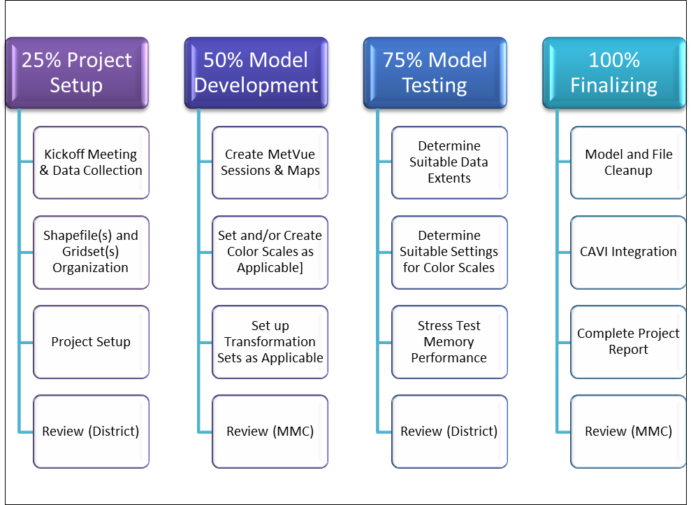
Figure 2-1. HEC-MetVue Work Flow
2.2.1 Project Setup (25 Percent Milestone)
The primary inputs for the HEC-MetVue model can be identified during the kickoff meeting and should be available from the CWMS local and national gridded meteorological databases. The HEC point of contact, the local district data system administrator, and HEC-MetVue modeler should work together on the collection and development of gridded data products.
Typically, gridded DSS database files are available on the district CWMS server and include products from the local NWS River Forecast Center (RFC). NWS products are also available through the USACE Cumulus (https://cumulus.rsgis.dev/) web service which processes national-scale NWS products into watershed scale gridsets in DSS. If the Cumulus catalog does not have real-time products and historic events of interest identified in the kickoff meeting, a data request can be submitted to CWMS-GriddedData-Support@usace.army.mil.
For watersheds where meteorological measurements gaging networks are more reliable than gridded products, or for historic events that precede the availability of gridded products (i.e., events of interest that precede the late 1990s), HEC-MetVue’s GageToTin utility should be used to automate the process of spatially interpolating gage observations of precipitation, temperature, and snow water equivalent (SWE), as needed. DSS monthly average precipitation grids can be a useful option to bias the precipitation spatial interpolation results. Monthly average precipitation data is available from https://prism.oregonstate.edu/normals/ and can be converted to DSS using HEC-MetVue. A digital elevation grid is a particularly useful option for temperature dataset interpolations, where elevation-based temperature lapse rate adjustments can be applied to the spatial interpolation results. If a DSS elevation grid is not readily available from the district or the MMC, The National Map (TNM) from the United States Geological Survey (USGS) is the best source ( https://apps.nationalmap.gov/downloader/#/) to obtain a raw DEM in GeoTIFF format. The DEM can be converted to ASCII format and projected to the standard hydrologic grid (SHG) system using ArcGIS, and then converted to DSS using HEC-MetVue.
Additionally, watershed shapefile(s) can be developed or obtained from local GIS repositories or local HEC-HMS models. For the 25 percent milestone, if the HEC-HMS basin delineations have not yet been finalized, USGS HUC8 watershed boundary shapefiles can be downloaded from https://apps.nationalmap.gov/downloader/#/ and used in the interim. A simple shapefile of regional states or the entire United States can also be a useful addition of background maps for watershed location reference.
The deliverable for the 25 percent milestone is an HEC-MetVue model setup up with standard polygon (not mutlipolygon) shapefiles added at the project defaults level, with the desired watershed shapefile(s) designated as a “basin average” map(s) and a regional states shapefile designated as a background map. The HEC-MetVue project directory structure must include one subdirectory called “maps,” containing the shapefiles for the watershed and background maps, and another subdirectory called “data” with sample files of gridded precipitation (and any other meteorological datasets needed for the project).
Once the initial HEC-MetVue model setup is complete, the modeler obtains the HEC-MetVue section of the project report template and complete all relevant sections. Any assumptions or issues concerning the initial setup of the model should be documented at this time.
Any comments received from the 25 percent milestone review are addressed and incorporated into the HEC-MetVue model and the draft HEC-MetVue section of the project report as needed.
2.2.2 Model Development (50 Percent Milestone)
Once the HEC-MetVue project is created, Sessions and Map Windows can be developed to represent CAVI Model Alternatives and corresponding meteorological datasets, respectively. Since HEC-MetVue is the primary input data provider for HEC-HMS, the HEC-MetVue modeler should coordinate with the HEC-HMS modeler to ensure the same DSS record pathnames (specifically the A-, B-, and C-parts) are used between the two models. Similarly, if an HEC-RAS model requires meteorological (e.g., precipitation, wind speed, and wind direction) data inputs from HEC-MetVue, DSS record pathnames consistency should be ensured between the HEC-MetVue and HEC-RAS models.
For rainfall runoff with no future rain modeling scenarios, an “Observed Precipitation Only” session (CAVI-MetVue Model Alternative) should be created with only one map window:
For rainfall runoff with forecast precipitation modeling scenarios, a “Forecast Precipitation” session (CAVI-MetVue Model Alternative) should be created with two map windows:
For snowmelt runoff with no forecast rain modeling scenarios, a “Snowmelt with No Forecast Precip” session (CAVI-MetVue Model Alternative) should be created with four map windows:
For snowmelt runoff with forecast precipitation scenarios, a “Snowmelt with Forecast Precip” session (CAVI-MetVue Model Alternative) should be created with five map windows:
For any of the scenarios described above, should an HEC-RAS model also require wind speed and wind direction data inputs, HEC-MetVue Map Windows should be added to link observed and forecast wind speed and wind direction datasets.
A color palette and scale combination should be assigned to each map window either by selecting default HEC-MetVue options for color palettes and scales, or by creating custom color palette and scale options.
When working with a forecast dataset that requires temporal transformation so that the dataset’s time interval matches the computational time interval, HEC-MetVue automatically applies equally weighted disaggregation. Typically, other desirable peaked patterns should be setup for the temporal disaggregation. If the Peaked_Start or Peaked_End patterns are setup and used, turning on the option to alternate the pattern between consecutive disaggregation time blocks can provide a scenario of maximum intensity over the disaggregation interval for the given forecast dataset.
There could also be situations where the time interval for the input meteorological dataset is smaller than the desired HEC-HMS computational timestep. In that case (e.g., having 15-minute observations and an HEC-HMS computational timestep of 1 hour), an HEC-MetVue temporal transformation set can be configured to aggregate the input data interval over the desired computational interval.
The deliverable for the 50 percent milestone is an HEC-MetVue model setup with sessions, map windows, sample datasets, and color palettes and scales selections, as well as transformation datasets as applicable. The modeler should obtain the HEC-MetVue section of the project report template and complete all relevant sections. Any assumptions or issues concerning the configuration of the HEC-MetVue model to support the needs of the HEC-HMS (and/or HEC-RAS) should be documented at this time.
Any comments received from the 50 percent milestone review are addressed and incorporated into the HEC-MetVue model and the draft HEC-MetVue section of the project report as needed.
2.2.3 Model Testing (75 Percent Milestone)
The functional HEC-MetVue model completed in the previous phase is tested in this phase to optimize its settings and performance.
In this phase, finalized HEC-HMS subbasin delineation shapefile(s) should be obtained and added to the HEC-MetVue project to replace any preliminary shapefiles previously used.
In addition, spatial data extents (from watershed extents to RFC extents and in between) should be evaluated to determine the most suitable spatial extent constraints to apply in the HEC-MetVue Map Window data reader. At minimum, the HEC-HMS watershed shapefile will provide the option to clip the input data to the watershed area extents, which guarantees the most efficient computations in HEC-MetVue and HEC-HMS models. To allow for what-if scenarios of spatial shifts and rotations of the input meteorological data while preventing lack of data coverage over the watershed area, another spatial clipping option or two should be provided with sufficiently buffered areal extents beyond the watershed. Typically, it would be most helpful to test with historic event datasets stored in the regional RFC spatial extents and evaluate a variety of spatial clipping extent constraints. Buffered shapefiles for spatial clipping extents greater than the watershed area can be generated using the HEC-MetVue Ad-Hoc Polygon Operations. Alternatively, ArcGIS can be used to create a buffered outline of the HEC-HMS watershed shapefile to use as another option for spatial clipping extents in the HEC-MetVue Map Window data reader.
Color palette and scale combinations per HEC-MetVue Map Window should be tested against datasets with a variety of time window durations (from one week or less to multiple weeks or even a few months) and a variety of possible value ranges (from normal to extreme events) for suitability of color palette and scale settings. Auto and explicit scales should particularly be evaluated for how well they reasonably distribute the range of values across the defined color palettes. Based on tests and evaluations, additional options of custom auto and/or explicit scales as well as corresponding custom color palettes should be developed.
For stress testing, it would help to obtain and work with as many records as expected to be used in real-time operations, such as a routine one-week to two-week forecast outlook or a few months of seasonal forecast outlook (typically from snow pack peak time to end of snowmelt season). In addition, stress testing should include using dataset spatial extents that are larger than clipped extents expected to be used in real-time operations.
The default maximum memory setting in the HEC-MetVue program configuration file is 3GB, which is more than sufficient for handling small (the size of Rhode Island) to medium (the size of New Jersey) spatial extents, and more than sufficient for handling gridded datasets for a small number of records (e.g., up to one week of roughly 700 15-minute records’ worth or up to one month of roughly 700 1-hour records’ worth).
However, provided that the user’s machine has a minimum of 16GB of installed memory, the HEC-MetVue memory settings must be increased to 6–8GB to better handle datasets with large spatial extents (e.g., the size of New Mexico or Texas or greater) and a large number of records (e.g., greater than one week of roughly 700 15-minute records’ worth or greater than one month of roughly 700 1-hour records’ worth). As the number of data points for higher resolution datasets with large spatial extents can easily be in the hundreds of thousands and even more than a million, high resolution gridsets with grid cell sizes of 1,000m or less will also require higher memory settings.
The HEC-MetVue model should be stress tested using a large number of records (as well as the largest spatial extents and time window duration expected to be used in this CWMS project), and through the evaluation of the performance of:
In summary, the focus of the HEC-MetVue stress testing is to determine the limits at which the program performance will suffer. HEC-MetVue comes preconfigured with a maximum memory heap setting of 3GB. Windows Task Manager can be used to monitor HEC-MetVue’s memory usage. Typically, when HEC-MetVue reaches the maximum amount of its allocated memory, the program performance will become extremely sluggish. If any sluggishness in HEC-MetVue or serious stalling of operations is observed and provided that the user’s machine has a minimum of 16GB of installed memory, the maximum heap settings can be increased (in the HEC-MetVue program configuration file) to 6GB and retested. For datasets with very large spatial extents and large number of records or high resolution grid cell size, an 8GB setting might be required. It is also good practice to constrain the data read extents with the option “Clip using polygon extents” (either by using the watershed shapefile or a slightly buffered polygon extent beyond the watershed) in the TIN or DSS selectors. In most cases, using the spatial extents clipping option precludes the need to increase the default maximum heap settings for HEC-MetVue.
The deliverable for this milestone is an HEC-MetVue project package with fully configured, applicable sessions and map windows along with settled options for spatial extents constraints on data reading and options for color palettes and scales. In addition, the HEC-MetVue project package should include all the test datasets used in setting up the various map windows and used in stress testing. The deliverable must also include recommendations on adequate program memory settings for the HEC-MetVue configuration file within the CAVI package.
Any comments received from the 75 percent milestone review are addressed and incorporated into the HEC-MetVue model and the draft HEC-MetVue section of the project report as needed.
2.2.4 Finalizing Plus Control and Visualization Interface Integration (100 Percent Milestone)
The functional HEC-MetVue model completed and tested outside the CAVI in the previous phase is imported and fully integrated into the CAVI in this phase.
In addition, per recommendations from the previous phase, adequate memory settings should be applied in the HEC-MetVue program configuration file within the CAVI software package.
Before importing the HEC-MetVue model into the CAVI, cleanup of the HEC-MetVue model package is required. Specifically, a great part of the input datasets used in setting up the various HEC-MetVue Map Windows and used in stress testing should be removed from HEC-MetVue project package and archived separately. The HEC-MetVue project package should only include light samples of the datasets expected to be handed off to other models in the CAVI. Additionally, any sessions and map windows not needed for the CAVI watershed application should be deleted.
Once the HEC-MetVue model is cleaned up and then imported into the CAVI watershed, the next step is to edit the CAVI-MetVue Model Alternative(s) and complete the configuration of the Input and Output tabs.
In each CAVI-MetVue Model Alternative’s input tab, the following is required:
- Observed data map windows should be assigned as “lookback,” while forecast data map windows should be assigned as “forecast.”
- When expected to serve an HEC-HMS model that uses the Hamon Evapotranspiration method, the HEC-MetVue observed temperature map window must use a start of simulation (SoS) offset of -1 day, while the forecast temperature map window must use an end of simulation (EoS) offset of +1 day.
- For basin average maps to become available in the CAVI-MetVue Model Alternative’s input tab, a polygon shapefile for the watershed must already be stored in a “Maps” subdirectory of the HEC-MetVue project directory within the CAVI watershed.
- For each map window entry, the input data pathname must match the pathname of the source data expected to be extracted from the database. Special care must be taken in selecting the appropriate duration for the input pathname, particularly for INST-VAL DSS gridded records for which the duration is zero.
- One output dataset must be created per variable (e.g., precipitation, temperature, or wind, etc.) expected to be provided to an HEC-HMS or an HEC-RAS model alternative. Applicable parameter, units, and time zone options should be selected. Most importantly, each output dataset must pair the complementary input Lookback Map Window and Forecast Map Window so they can be computed and output as a single dataset to handoff to HEC-HMS or HEC-RAS.
- For cases where the CAVI watershed is built in a non-GMT time zone, each output dataset should be assigned the time zone used for the CAVI watershed.
- For each output dataset, special care must be taken in selecting the proper output
settings:
- The output time interval must match the expected compute interval of the HEC-HMS model or HEC-RAS model that HEC-MetVue will serve.
- The output parameter type must be set based on the appropriate DSS conventions and what the HEC-HMS or HEC-RAS models need. For example, PER-CUM is the typical output parameter type for a precipitation dataset, while INST-VAL is the typical output parameter type for temperature and snow datasets.
- It is highly recommended to select the watershed’s shapefile for clipping the output extents.
- For DSS grid outputs, SHG is the typical projection setting that should be selected. The output pathname (A-Part, B-Part, C-Part, and Interval) should match exactly what the HEC-HMS or HEC-RAS models are expecting as input from HEC-MetVue.
- For time series generation:
- Choosing the option to Write to Forecast DSS can be used to provide time series inputs for non-gridded HEC-HMS methods. HEC-MetVue time series generation is also particularly useful for providing observed basin averages for HEC-HMS snow models to help with evaluating HEC-HMS computed SWE basin averages against observed averages.
- The Write to Forecast DSS option can also provide HEC-RAS model time series meteorological boundary conditions if needed.
- The Tabulate to File option can be a nice addition as it provides a text summary report output of basin average computations.
Once the CAVI-MetVue Model Alternative(s) configuration is completed, the next steps include:
- Setting the CAVI-MetVue model alternative key(s).
- Adding the CAVI-MetVue model alternative(s) to a CAVI forecast run(s).
- Cross checking the CAVI-MetVue model alternative(s) input datasets in CAVI’s model linking editor.
- Creating extract groups for observed and forecast gridded dataset inputs as needed by the CAVI-MetVue model alternative(s).
- CAVI-MetVue model alternative data preprocessing and computations should be tested through newly created CAVI forecast simulations and gridded dataset extracts with short range (under 1 week), medium range (2 to 4 weeks), and seasonal range (2 to 6 months) time windows as applicable for the expected real-time operational and seasonal planning use of the final CAVI watershed.
- Prepare the CAVI-MetVue model alternative to assist with stress testing of other CAVI model alternatives (HEC-HMS, HEC-ResSim, and HEC-RAS) using hypothetical scenarios of extreme events and, if available, actual extreme event datasets:
- Create and compute a test CAVI simulation(s) and rely on HEC-MetVue ad-hoc dataset manipulation (factoring of the grid dataset and or applying spatial shifts and rotations) to generate plausibly intensified magnitudes of historic event(s) that are readily available from the district’s CWMS or cumulus gridded databases.
- Optionally, also create and compute a test CAVI simulation(s) using an extreme event(s) that can potentially be available from the UACE Extreme Storms Database (https://maps.mmc.usace.army.mil/esd/) or online sources.
The deliverables for this milestone are a fully integrated and tested HEC-MetVue project and CAVI-MetVue model alternative(s) within the CAVI watershed. The CAVI-MetVue watershed must include a clean and slim HEC-MetVue project with fully configured, applicable sessions and map windows. The CAVI-MetVue project package should only include light weight samples of the datasets used in setting up the various map windows and stress testing. The CAVI-MetVue watershed should also include test CAVI forecast simulations, including extreme event tests if possible.
Any comments received from the 100 percent milestone review are addressed and incorporated into the HEC-MetVue model and the draft HEC-MetVue section of the project report as needed.
Section 3 - HEC-HMS Model Development
This section describes the purpose, requirements, products, and standards for HEC-HMS model development for CWMS implementation. This section also describes basic processes to follow when developing HEC-HMS models for use within CWMS. This section is not intended to provide a step-by-step guide for this process and is written assuming the reader has a moderate understanding of HEC-HMS.
3.1 Modeling Objective
The HEC-HMS modeler’s objective is to develop a model capable of accurately simulating runoff in the watershed for a wide range of hydrologic events in a reasonable amount of computation time. Development of the HEC-HMS model for CWMS is an important step in the modeling process, as subsequent HEC-ResSim, HEC-RAS, and HEC-FIA models are based, in large part, on output from the HEC-HMS model.
3.2 Modeling Milestones
The HEC-HMS modeler prepares intermediate deliverables and provides them for review at key production points of the model development. A brief description of the milestones is provided in Sections 3.2.1-3.2.4. In addition, Figure 3-1 provides a workflow diagram of the process.
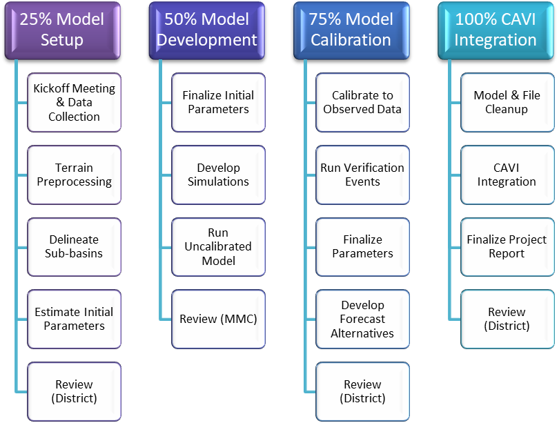
Figure 3-1. HEC-HMS Modeling Workflow
3.2.1 Model Setup (25 Percent Milestone)
Many of the preliminary inputs for the HEC-HMS model are developed using the GIS tools available in HEC-HMS. These tools transform the drainage paths, gridded terrain, and watershed boundaries of the watershed into a hydrologic data structure that represents the drainage network.
The deliverable for the 25 percent milestone is a georeferenced basin schematic of the watershed, including all sub-basins, junctions, diversions, and other significant features.
3.2.2 Model Development (50 Percent Milestone)
Once the basin model is developed, the remaining components of an HEC-HMS model that need to be created are the meteorologic model, control specifications, time-series data, paired data, and gridded data. Many computational options are available in HEC-HMS for baseflow, routing, precipitation, loss rates, and transformations. Appropriate options are selected for the watershed and the initial parameter estimates are computed using GIS datasets and information from existing models.
The deliverable for the 50 percent milestone is an uncalibrated HEC-HMS model that runs without any major errors or warnings.
NOTE
Only one HEC-HMS model should be developed. The model can have multiple basin models within the HEC-HMS model that represent various conditions, such as wet/dry antecedent moisture conditions; however, it should all be included within one HEC-HMS project. The CAVI will not recognize the correct files if multiple HEC-HMS projects exist.
3.2.3 Model Calibration and Verification (75 Percent Milestone)
The HEC-HMS model developed in the previous milestone is calibrated to more accurately compute runoff timing, volume, and peak flow values for several historic events. The model is then validated to ensure it is producing reasonable output for events not used during the calibration process. The modeler configures zones within the HEC-HMS model and ensures the slider bar capability for real-time calibration is set up prior to CAVI integration.
The deliverable for the 75 percent milestone is a fully calibrated HEC-HMS model that includes observed stream flow and precipitation data for several historic events.
3.2.4 Control and Visualization Interface Integration (100 Percent Milestone)
Once the model is calibrated and validated, the model is cleaned up to remove excess files and data and is then incorporation into the CAVI. The HEC-HMS alternatives are tested in the CAVI by running forecasts to ensure it performs as designed.
The deliverable for the 100 percent milestone is the final HEC-HMS model that has been integrated into the CAVI and the completed HEC-HMS section of the project report.
3.3 Model Setup (25 percent Milestone)
The modeler will use the GIS tools within HEC-HMS to delineate sub-basins and stream networks and calculate hydrologic parameters based on land use and soil databases. These characteristics are the foundation upon which the final HEC-HMS model is built.
The deliverable for the 25 percent milestone is the initial HEC-HMS basin model schematic. All sub-basin and reach delineation must be finalized before moving past the 25 percent milestone. The district must agree to the delineation at this point, as any sub-basin or reach refinement during later stages of the project may require significant changes to all models being developed.
3.3.1 Data Sources and Collection
The CWMS GIS team member will provide most of the pre-model data needed to build a hydrologic model. Although terrain data is the minimum data requirement to use the GIS tools within HEC-HMS, other datasets contain important information for constructing the hydrologic model. Detailed information on data sources can be found in Section 1 of this technical manual.
3.3.1.1 Terrain Data
Terrain data used for HEC-HMS model development is the USGS 30-meter NED, unless the watershed is small enough to justify the use of higher resolution data. Terrain data is provided to the CWMS modeling team by the CWMS GIS team member.
It may be necessary to improve the DEM using enhanced resolution data in areas of flat terrain to force hydrologically-correct subdivision of the watershed. Higher resolution data may be available from the district and can supplement the NED dataset if needed.
The terrain data may be re-sampled to a larger cell size to keep the overall file size of the DEM small. In most cases, DEMs with large file sizes can be resampled to a coarser resolution without sacrificing accuracy or precision of the final HEC-HMS model. See Section 3.3.2 for further information.
3.3.1.2 Stream Flow Gages
Stream gages that are useful for hydrologic calibration should be included in the HEC-HMS project. The locations of stream gages are useful in identifying key computation points in the watershed. The CWMS GIS team member will provide a preliminary dataset of the gages within the watershed. If pertinent gages are missing from the dataset, the gage locations can be added by using latitude and longitude coordinates. The majority of stream flow gages are maintained by the USGS ( https://waterdata.usgs.gov/nwis), USACE, state governments, or flood control districts.
3.3.1.3 Stream Alignments
As discussed in Section 1.7.3, the CWMS GIS team member is responsible for providing the preliminary stream alignment shapefile to the PDT. Once the final stream alignment is approved by the district and PDT, it is ready to use for setup of the watershed within HEC-HMS.
3.3.1.4 Land Use Data
Land use data can be used to estimate levels of imperviousness and other HEC-HMS basin model parameters. The USGS Land Use Land Cover (LULC) dataset provides good coverage, but may be outdated ( https://www.usgs.gov/core-science-systems/eros/lulc). State GIS websites can also be a source of land use data.
3.3.1.5 Soil Coverage
Soil coverage is useful for estimating infiltration rates and other HEC-HMS basin model parameters. The Soil Survey Geographic Database (SSURGO) contains soil data at the county level and the State Soil Geographic Database (STATSGO) contains soil data at the state level ( https://www.nrcs.usda.gov/wps/portal/nrcs/main/soils/survey/geo/). Gridded SSURGO (gSSURGO) is also available for use by the HEC-HMS modeler ( https://gdg.sc.egov.usda.gov/). The modeler should decide which dataset is appropriate to use for the watershed.
3.3.1.6 Hydrologic Unit Code
The hydrologic unit code (HUC) contains the major watershed boundaries as published by the USGS ( https://www.nrcs.usda.gov/wps/portal/nrcs/main/national/water/watersheds/dataset/). The HUC shows watershed boundaries at six levels of detail, ranging from local to regional drainage area, and can be a good check on the accuracy of the initial sub-basin delineations. These boundaries may also be used to force the delineation of sub-basins within the HEC-HMS model if needed.
3.3.2 Preprocessing Terrain Data
Terrain preprocessing marks the first step in the development of an HEC-HMS project. In this step, a DEM is used as an input to derive additional datasets that collectively describe the drainage pattern of the watershed and allow for subsequent stream and sub-basin delineation.
The HEC-HMS modeler should load the final terrain dataset described in Section 3.3.1.1 into the project and link it to the appropriate basin model. The GIS delineation tools within HEC-HMS are used to fill sinks, develop the flow direction and flow accumulation grids, and identify the streams within the basin. Refer to the HEC-HMS Tutorials and Guides ( https://www.hec.usace.army.mil/confluence/hmsdocs/hmsguides) for more information.
3.3.3 Performing Initial Sub-basin Delineation
The HEC-HMS modeler will first define the study area by identifying the outlet of the basin. The modeler may choose to add additional break points within the watershed at this point, but it is not necessary to continue the delineation process. Once the modeler defines the outlet, they can delineate the elements within the basin.
Sub-basin and stream delineation is an iterative process, but a quality control check after initial delineation will help ensure that the delineation process is working properly and that no major errors exist with the terrain data.
HUC sub-basin boundaries and NHD stream alignments provide a baseline against which the HEC-HMS delineations can be compared. Significant variation from the published data may indicate an error in the DEM or the need to refine the terrain data even further. This can be accomplished by burning in streams or building walls. Refer to the HEC-HMS Tutorials and Guides for more information.
3.3.4 Refining Sub-basin Delineation for Project Flow Locations
The initial sub-basin and stream delineation should be reviewed and modified to fit the district’s preferences. Sub-basins can be merged or split using the GIS tools in HEC-HMS to obtain the desired configuration. Things to consider when refining the initial delineations are the location of gages, reservoirs, and common computation points. It is very important for the HEC-HMS modeler to remember that the primary use of this model is for real-time forecasting, so they should favor simplicity to ensure that the model is easy to calibrate and runs within a reasonable time.
3.3.5 Initial Model Layout Review
Once the sub-basin delineation is complete, the team should review the initial model layout. The HEC-HMS modeler will meet with the HEC-ResSim, HEC-RAS, and HEC-FIA modelers to review the layout and ensure the sub-basins are delineated at all required locations. The purpose of this review is to ensure data transfer from one model to another is capable at all necessary locations. The 25 percent HEC-HMS reviewer should also review the initial model layout and verify it will meet the needs of the water management office.
3.3.6 Identifying and Assigning Element Names
The HEC-HMS modeler identifies and assigns names to sub-basins, junctions and reaches in the model according to the agreed upon naming conventions. The modeler provides the shapefiles (including names of all components) to the other team members and district for their approval.
In general, sub-basins are named in the following priority:
- Gage name at outlet
- Reservoir name at outlet
- Town at or near outlet
- Creek or stream entirely within sub-basin
- Large city or town in sub-basin
- Street or similar location name at outlet
Reach names are generally the name of the upstream element followed by a dash and then the name of the downstream element. It is up the modelers and district on how reaches should be named.
3.3.7 Computing Watershed Characteristics
Once the stream and sub-basin delineation is finalized, the modeler can compute physical characteristics of the watershed using automated tools within HEC-HMS. Physical characteristics for a stream include the length, slope, relief, and sinuosity. Similarly, physical characteristics for the sub-basins include the longest flowpath length and slope, centroidal flowpath length and slope, and overall basin slope and relief. These physical characteristics will be used to estimate the initial model parameters as explained in Section 3.3.8.
3.3.8 Estimating Model Parameters
The HEC-HMS modeler can use the physical characteristics of the watershed elements along with additional GIS datasets (soil data, LULC, etc.) to estimate the initial model parameters. Hydrologic parameters, such as the percent impervious area and time of concentration, can be computed using the Expression Calculator in HEC-HMS. Refer to the HEC-HMS Tutorials and Guides for more information.
The loss and transform methods to be used in the HEC-HMS model were discussed during the kickoff meeting and documented within the HEMP. The HEC-HMS modeler can estimate the initial loss and transform parameters by using the Expression Calculator. Depending on which methods are chosen, the required parameters and computations will vary. Links to various HEC-HMS tutorials and guides can be found in Section 12.
3.3.9 Reviewing Initial Model Setup
Before submitting the HEC-HMS model for review, the modeler should review the initial setup and parameterization of the model by confirming all hydrologic elements are properly connected and element characteristics such as sub-basin area have been properly computed. As a reminder, only one HEC-HMS model should be created for each watershed.
3.3.10 Documentation of Model Setup
Once the model setup is complete, the modeler should obtain the HEC-HMS section of the project report template and complete all relevant sections. Any assumptions or issues concerning the initial setup of the model should be documented at this time.
3.3.11 Interim Model Review (25 Percent Milestone Review)
Once the initial HEC-HMS project has been created, the modeler completes the 25 percent portion of the MMC HEC-HMS review checklist. The modeler uploads a zipped copy of the preliminary model, the draft HEC-HMS section of the project report, and the completed review checklist to the corresponding milestone folder on ProjectWise and submits the package for interim review.
3.3.12 Incorporating Review Comments
Any comments received from the 25 percent milestone review are addressed and incorporated into the HEC-HMS model and the draft HEC-HMS section of the project report as needed.
3.4 Model Development (50 Percent Milestone)
Once the schematic has been reviewed and approved, a meteorologic model and corresponding control specification are developed to complete the HEC-HMS project. A basin model from an existing HEC-HMS project can be used if it meets MMC standards. The model is not calibrated, but should incorporate all major data linkages, contain reasonable initial parameters estimates, and run without errors and significant warnings
The deliverable for the 50 percent milestone is a fully developed, uncalibrated HEC-HMS project for the watershed.
3.4.1 Finalizing Initial Parameter Estimates
If any hydrologic parameters were not estimated during the 25 percent phase, the HEC-HMS modeler will need to enter them into the model at this time. Model parameters can be estimated from GIS datasets, regional regression equations, and existing models. The modeler should ensure the local flow option is set to yes.
3.4.1.1 Baseflow Methods and Parameters
The baseflow method should have been decided upon during the kickoff meeting. Typically, the recession baseflow method is chosen for HEC-HMS models used for real time forecasting. Modelers should refer to HEC-HMS online tutorials when setting up the initial parameters.
3.4.1.2 Reach Routing Methods and Parameters
The routing methods used in the HEC-HMS model will depend on district preference and availability of data from the HEC-RAS model. Though the lag method is easiest to use, it should be the last option considered. Where the HEC-RAS cross sections overlap the HEC-HMS routing reaches, Mod-Puls or Muskingum-Cunge routing methods can be used. The HEC-HMS modeler should obtain the necessary data from the HEC-RAS modeler even though the model is uncalibrated at this point. Refer to Engineering Manual (EM) 1110-2-1417, Flood Runoff Analysis, for further information. Modelers can also refer to HEC-HMS online tutorials for further guidance.
Routing methods and parameters in the HEC-HMS model need to match those in the HEC-ResSim model; if they do not, there can be discrepancies in computed hydrographs from the two models.
3.4.2 Adding Observed Flow
Observed flow data from historic events is added to the model through the Time-series Data Manager. The modeler creates a new time-series data entry for each gage location and populates the name and description with the corresponding information for the gage. A time-series gage entry for each gage location should also be created at this time. The gage names are chosen so they are easily identifiable, and the actual gage name and USGS ID (if applicable) are included in the description field. Observed data for each gage is entered in the Component Editor and is associated with the corresponding basin model element.
Once the observed data is associated with the proper basin element, the element should be set as a computation point so that the element can be easily identified and used to perform more efficient computations during calibration and real-time forecasting simulation runs. Computation points can be used to speed up calibration efforts as HEC-HMS will compute only the modified elements upstream of the computation point.
3.4.3 Creating Meteorologic Models of Historic Events
The modeler creates meteorologic models for historic events using precipitation data available for the watershed. This meteorologic data is used later in the calibration process, but also allows for creation of simulation runs to ensure the HEC-HMS project runs and is stable. Radar-gage ensemble products (i.e., the Multisensor Precipitation Estimator (MPE)) are the preferred gridded precipitation inputs, but precipitation gage data can be utilized if radar-gage ensemble products are not available. HEC-MetVue can be used to convert the point precipitation data into a gridded product that the HEC-HMS model can use.
Gridded data is added by creating a new precipitation gridset in the Grid Data Component Manager. Once created, the appropriate filename and path for the gridded data should be entered in the Component Editor. If the district cannot provide gridded precipitation data for the calibration events, modelers should refer to the HEC-HMS online guidance on obtaining gridded data products ( https://www.hec.usace.army.mil/confluence/hmsdocs/hmsguides/working-with-gridded-boundary-condition-data/gridded-data-sources).
Once a precipitation gridset is created and added to the HEC-HMS project, a meteorologic model for that gridset is created using the Meteorologic Model Manager. The modeler selects the appropriate precipitation gridset and enters a description for the meteorologic model in the Component Editor. All DSS files with observed data should be saved within the HEC-HMS project folder. When the DSS files are in the HEC-HMS project folder, HEC-HMS uses a relative pathname for the DSS file.
Please refer to Appendix 3.1.7 for more information regarding snowmelt modeling.
3.4.4 Creating Simulations of Historic Events
Once the basin model and meteorologic model are created, a control specification is created to perform a model simulation. The control specification file identifies the dates and times for which the simulation is run and should match the precipitation event of interest in the meteorologic model. If there is more than one rainfall event of interest in the meteorologic data, a control specification is created for each event. Control specifications are only used during HEC-HMS setup and calibration, because CWMS automatically generates control specifications for each forecast alternative once the HEC-HMS model is incorporated into the CAVI.
The simulation time-step is also defined in the control specification. For most models, a time-step of one hour is appropriate. Ideally, the time-step is based on sub-basin unit hydrograph and routing reach parameters. The simulation time step determines the number of ordinates that define the runoff hydrograph. A general rule of thumb is at least 4 points (ordinates) on the rising limb of the hydrograph are required to adequately define the shape. In the case of the unit hydrograph, a sub-basin with a time of concentration of one hour requires a simulation time-step of 15 minutes or less.
Once the basin model, meteorologic model, and control specifications have been set up, a simulation run is created for each historic calibration event. The simulation runs should be named so that they are easily identifiable. For example, a simulation name of “Calibration May 2010” identifies the simulation as a calibration of the May 2010 flood event.
3.4.5 Running the Uncalibrated Model
Once the simulation runs are created, the HEC-HMS modeler computes each simulation and reviews the message logs to determine if there are any major warnings to address. If no major warnings are found, output from the model at the basin outlet and locations of interest (gage locations, CCPs, etc.) are examined to determine if the model is functioning properly. The modeler verifies the observed flows are plotting correctly in the results for all of the gage locations with observed data.
3.4.6 Documentation of Model Development
Once the initial HEC-HMS model development is complete, the modeler should obtain the draft HEC-HMS section of the project report completed for the 25 percent milestone and update the report as necessary. Any assumptions or issues concerning the initial development of the HEC-HMS model should be documented at this time.
3.4.7 Interim Model Review (50 Percent Milestone Review)
Once the initial HEC-HMS simulations have been successfully run, the modeler completes the 50 percent portion of the MMC HEC-HMS review checklist. The modeler then uploads a zipped copy of the uncalibrated HEC-HMS model, the draft project report, and the completed review checklist to the corresponding milestone folder on ProjectWise and submits the package for interim review.
3.4.8 Incorporating Review Comments
Any comments received from the 50 percent milestone review are addressed and incorporated into the HEC-HMS model and draft HEC-HMS section of the project report as needed.
3.5 Model Calibration and Verification (75 Percent Milestone)
Once the HEC-HMS project is developed and running, the basin model is further refined to obtain a calibrated model. Ideally, the modeler calibrates the model as it would be during a real-time forecast; parameters for multiple elements upstream of a gage are adjusted in parallel until the simulated results match observed gage records. The goal is to adjust model parameters such that model output matches the peak, timing, and/or runoff volume of historic events. Once calibrated, the model is then verified using other historic events.
The deliverable for the 75 percent milestone is a calibrated and verified HEC-HMS model.
3.5.1 Calibration of Model using Historic Events
Observed streamflow and precipitation data are necessary inputs when creating a calibration trial. One historic event was created during the previous stage of model development, but other events will be added to the HEC-HMS project to aid in calibration. If calibrating for numerous events, multiple basin models should be created to track parameters during calibration. It is recommended that the model be calibrated to historic events with both wet and dry antecedent conditions. This allows the modeler to determine minimum and maximum values for each parameter in the HEC-HMS model.
Only events for which reliable gridded precipitation data and streamflow records are available are used for calibration. It is suggested to focus calibration of the HEC-HMS model on recent events to ensure the basin characteristics during the historic event are similar to current conditions. If historic data has not already been collected, it can be obtained and processed from the sources described in the watershed’s HEMP.
If the HEC-RAS model is a source of data for the routing parameters, calibration of the HEC-HMS model is an iterative process. The modeler should attempt to calibrate the model with the initial routing parameters provided by the HEC-RAS modeler, adjusting other parameters in the model to match observed records. Once a calibration run is complete, the HEC-HMS modeler should provide a revised output DSS file to the HEC-RAS modeler for calibration of the hydraulic model. Once the HEC-RAS modeler calibrates the model, they should examine the routing parameters with the HEC-HMS modeler to see if the parameters have changed significantly and it warrants another calibration run through the HEC-HMS model. This process should be repeated until the HEC-RAS and HEC-HMS modeler are both confident that their models are calibrated for the historic event they are simulating.
If the HEC-HMS model was calibrated to multiple wet and dry antecedent condition events, the parameter values for each should be averaged to obtain the average wet and average dry values for the model.
3.5.2 Verification of Model using Historic Events
Once the HEC-HMS model is calibrated to several historic events, model accuracy is verified by running other storm events that were not used in the calibration of the model. The verification events are entered into the HEC-HMS project as observed data (streamflow and precipitation) and a new control specification and simulation are created for each event.
The HEC-HMS modeler compares output from the verification runs to the observed streamflow data. If the simulation does not adequately match the observed data, further adjustment to model parameters may be needed using the same procedure described for the calibration process in Section 3.5.1. This may be an iterative process until reasonable calibration targets are met for all verification events.
3.5.3 Development of Forecast Alternatives
The HEC-HMS modeler must create forecast alternatives for each basin condition (e.g., dry or wet). An HEC-HMS forecast alternative is the HEC-HMS compute type that is recognized by the CAVI. HEC-HMS forecast alternatives are created in the HEC-HMS standalone model and will be accessible in the CAVI after the model has been imported.
3.5.4 Stress Testing Using Extreme Events
To ensure the model is robust enough to handle extreme precipitation events, the modeler should run a very large event, such as a probable maximum precipitation (PMP) event, through the HEC-HMS model. This test verifies that the routing parameters can handle extreme events. Modelers should focus on the routing parameters to ensure the model can compute without errors or warnings.
3.5.5 Documentation of Model Calibration and Verification
Once the calibration and verification of the HEC-HMS model is complete, the modeler should obtain the draft HEC-HMS section of the project report completed for the 50 percent milestone review and update the report as necessary. Any assumptions or issues concerning the calibration and verification of the HEC-HMS model should be documented at this time.
3.5.6 Interim Model Review (75 Percent Milestone Review)
Once the calibration of the HEC-HMS model is complete, the modeler completes the 75 percent portion of the MMC HEC-HMS review checklist. The modeler uploads a zipped copy of the calibrated model, the draft HEC-HMS section of the project report, and the completed review checklist to the corresponding milestone folder on ProjectWise and submits the package for interim review.
3.5.7 Incorporating Review Comments
Any comments received from the 75 percent milestone review are addressed and incorporated into the HEC-HMS model and the draft HEC-HMS section of the project report as needed.
3.6 Control and Visualization Interface Integration (100 Percent Milestone)
Calibration and verification of the HEC-HMS model concludes major model development. The remaining tasks primarily focus on preparing the model for incorporation into the CAVI.
The deliverables for the 100 percent milestone are final HEC-HMS model integrated into the CAVI watershed and the final HEC-HMS section of the project report.
3.6.1 Model Cleanup
Before transferring the HEC-HMS model to the CAVI modeler, the modeler uploads a complete copy (zipped) of the HEC-HMS model including all calibration and validation runs to ProjectWise. The HEC-HMS modeler then creates a clean copy of the model for import into the CAVI. To accomplish this, the modeler deletes any extraneous project files such as output and log files, output DSS files, DSS files containing calibration data (especially gridded data), or other data not necessary for CAVI integration. Any basin models not needed for real-time use are also deleted at this time. To the extent possible, the HEC-HMS interface is used to clean up files, as manual manipulation of files may inadvertently corrupt the model.
3.6.2 Control and Visualization Interface Integration
Once the HEC-HMS model directory is cleaned up, the CAVI modeler and HEC-HMS modeler work together to import the final HEC-HMS model into the CAVI. See Section 7.4.1 for further instructions.
3.6.3 Documentation of Model Development
The HEC-HMS section of the project report should be almost complete at this point, as it builds on the draft report written for the previous project milestones. Any additional information or items of interest not previously discussed are added to the report as needed. Documentation of any unresolved issues that may impact real-time operations or model results is important.
3.6.4 Final Model Review (100 Percent Milestone Review)
Once the HEC-HMS model has been finalized, the modeler completes the 100 percent portion of the MMC HEC-HMS review checklist. The modeler uploads a zipped copy of the final model, the final HEC-HMS section of the project report, and the completed review checklist to the corresponding milestone folder on ProjectWise and submits the package for final review.
3.6.5 Incorporating Review Comments
Any comments received from the 100 percent milestone review are addressed and incorporated into the HEC-HMS model and the final HEC-HMS section of the project report as needed.
3.6.6 Testing Model within the Control and Visualization Interface
The HEC-HMS modeler and CAVI modeler work together to ensure the HEC-HMS model is functioning properly within the CWMS CAVI environment. The HEC-HMS modeler reviews all model linking within the CAVI to ensure HEC-HMS is obtaining the correct inputs. The HEC-HMS modeler is also responsible for reviewing model results computed in the CAVI and quickly verifying model calibration.
3.6.7 Final Model Storage
Once the modeling is complete, the HEC-HMS model and all supporting files are zipped and uploaded to the corresponding folder on ProjectWise. As described in Section 3.6.1, the version of the HEC-HMS model that includes all calibration and validation runs and associated data should be zipped and uploaded to ProjectWise. The clean version of the HEC-HMS model for import into the CAVI watershed should also be zipped and uploaded to ProjectWise. The files should be named so that it is easy to distinguish between the two versions. It is the responsibility of the modeler to upload all files relating to the development of the HEC-HMS model for final storage on ProjectWise at the end of the project.
3.7 Reference Material
The following sources may be helpful to team members developing the HEC-HMS model. Team members can locate these sources by following the citation information found in Section 12.
- Engineer Manual (EM) 1110-2-1417, “Flood Runoff Analysis”
- HEC-DSSVue User’s Manual
- HEC-HMS User’s Manual
- HEC-HMS Technical Reference Manual
- HEC-HMS Applications Guide
- HEC-HMS Tutorials and Guides
- CWMS User’s Manual
- PROSPECT Course Materials
- Hydrologic Modeling with HEC-HMS
- Advanced Applications of HEC-HMS
Section 4 - HEC-ResSim Model Development
This section describes the purpose, requirements, products, and standards for HEC-ResSim model development for CWMS implementation. This section also describes basic processes to follow when developing HEC-ResSim models for use within CWMS. This section is not intended to provide a step-by-step guide for this process and is written assuming the reader has a moderate understanding of HEC-ResSim.
4.1 Modeling Objective
The HEC-ResSim modeler’s objective is to develop a model capable of accurately simulating reservoir operations for a wide range of hydrologic events. In CWMS, the HEC-ResSim model is intended to be used by the district water managers to aid in development of a release schedule for the projects they regulate. As such, the model should represent the operational goals and constraints that guide the regulators’ decisions, be easy to update and maintain, and compute quickly.
4.2 Modeling Milestones
The HEC-ResSim modeler prepares intermediate deliverables and provides them for review at key
production points of the model development. A brief description of the milestones is provided in
Sections 4.2.1–4.2.4. In addition, Figure 4-1 provides a workflow diagram of the process.
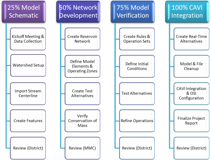
Figure 4-1. HEC-ResSim Modeling Workflow
4.2.1 Model Schematic Creation (25 Percent Milestone)
The HEC-ResSim modeler will work with the district to obtain all critical information and data needed for the model. The modeler is responsible for collaborating with district personnel to ensure they obtain the most up-to-date physical and operational data.
The deliverable for the 25 percent milestone is a complete watershed schematic developed in the Watershed Setup module of HEC-ResSim.
4.2.2 Reservoir Network Development (50 Percent Milestone)
The HEC-ResSim network must have the physical data of the reservoirs completed and verified. Each reservoir must include a preliminary operation set in which all operational zones are defined. All inflows must be identified at the junctions and the reaches must have preliminary routing specified. All elements must be named following the naming convention.
The deliverable for the 50 percent milestone is a validated but uncalibrated HEC-ResSim model that computes without error and maintains conservation of mass throughout the network of rivers and reservoirs.
4.2.3 Development and Verification of Reservoir Operations (75 Percent Milestone)
The watershed includes simulations of each alternative through the calibration time window.
The deliverable for the 75 percent milestone is a complete and verified reservoir model that includes alternatives that reflect the reservoir operation scenarios required by the district.
4.2.4 Control and Visualization Interface Integration (100 Percent Milestone)
The HEC-ResSim modeler assists the CAVI modeler with importing a cleaned-up version of the final HEC-ResSim model into the CWMS CAVI and ensuring the model is functioning properly within the CWMS framework.
The deliverable for the 100 percent milestone is the final HEC-ResSim model that has been integrated into the CAVI watershed and the completed HEC-ResSim section of the project report.
4.3 Model Schematic Creation (25 Percent Milestone)
The initial setup of the HEC-ResSim model includes the development of the watershed schematic. The watershed schematic is common to both HEC-ResSim and the CWMS CAVI, so it must cover the full extent of all models and data acquisition sites. Creation of the schematic includes defining the watershed configuration, importing the stream alignment, creating the model schematic elements (reservoirs, computation points, diversions, etc.) and naming them according to the agreed-upon naming convention.
The deliverable for this milestone is a complete watershed schematic developed in the Watershed Setup module of HEC-ResSim.
4.3.1 Kickoff Meeting, Initial Model Setup, and Data Requirements
The kickoff meeting is an important step in the model development process. Several important decisions that impact reservoir model development are made at this meeting, including identification of:
- Watershed extents
- Gage locations and control points
- All reservoirs to be modeled within HEC-ResSim
- Hydrologic routing methods
- Reservoir management scenarios required by district water managers
- Computational time step
- Calibration and validation events.
A naming convention consistent across all models should be established during the meeting that covers the various locations and model elements found within the watershed.
Data collection involves gathering and reviewing all information related to the reservoirs, diversions, streams, and control points within the river network. This information can be taken from WCMs, design memorandums, spreadsheets, and district water managers or operating partners. Historic data may be obtained from hydrologic databases (USGS, USACE, NWS, etc.). Any existing reservoir models for the watershed are also collected and reviewed as part of this process.
Data required for the HEC-ResSim modeling process include:
- Reservoir data—elevation/storage/area relationship (area only needed if computing free water surface evaporation and/or seepage), inflow, outflow, evaporation (if applicable), and seepage (if applicable)
- Reservoir outlet/spillway data—outlet/spillway release capacity
NOTE
The storage and release capacity curves should extend up to or beyond the top of the dam or to the maximum pool elevation during a probable maximum flood, whichever is higher. These curves should also extend down to zero storage or zero release capacity, but, at a minimum, they should be below the bottom of operating storage.
- Reservoir operating criteria—rules, pool zones
- Dam characteristics—crest length, top of dam elevation
- Project design information—PMF or design storms
- Hydropower—flow and generation capacity, efficiency, headloss, tailwater rating curve, and operating restrictions/criteria (e.g., Scheduling, contract requirements)
- Downstream operating criteria—control points, downstream flow limits and/or requirements, and routing information/travel times
- Gage information—USGS, United States Bureau of Reclamation (USBR), USACE, NWS, state, or local entity
- Diversions—from the reservoir pool and/or the downstream river system
Initial model setup involves creating a watershed schematic that identifies the reservoirs, rivers, levees, computation points, etc. that are being modeled by the overall CWMS effort. The watershed schematic is common to both HEC-ResSim and the CWMS CAVI so it must cover the full extent of all models and data acquisition sites, not just the extent to be modeled within HEC-ResSim.
The modeler creates the watershed schematic in the Watershed Setup module of HEC-ResSim. Steps for creating the schematic include importing the stream alignment, adjusting each stream’s flow direction as needed, connecting the streams at the stream confluences, creating model schematic elements (reservoirs, computation points, diversions, etc.), and naming them according to the agreed upon naming conventions.
4.3.2 Watershed Setup Module
The watershed schematic is common to both HEC-ResSim and the CWMS CAVI. It must cover the full extent of the basin to be represented by the combination of all models.. The modeler should not begin creating the schematic in the HEC-ResSim model until both the stream alignment and set of common computation points are final.
The basic steps to create the watershed configuration and schematic are:
- Create a new watershed. The watershed name should follow the MMC naming guidelines, but it is suggested that it does not match the CWMS CAVI watershed name.
- Add Maps. Recommended maps to include: sub-basin outline from HEC-HMS, final stream alignment, gage locations, computation points, and geopolitical boundaries (states, counties, cities, etc.).
- Import the final stream alignment agreed upon by all team members.
- Stream alignments should be identical for all models. Ensure all team members and the district agree before the shapefile is finalized.
- Stream alignments should cover all model extents but should only be as detailed as necessary for all models. The shapefile should be generalized by the GIS team member to remove extraneous points.
- The streams in the stream alignments should be continuous and not broken into reaches. For example, the alignment should be continuous across a junction (not split where a tributary connects to the main stem).
- Verify the flow direction of each stream in the stream alignment and correct as needed.
- Verify the connection of the streams at each confluence and complete the connectivity if needed.
- Create a watershed configuration. If not addressed in the naming conventions, name it Existing.
- Draw in model elements and name each element following the team’s naming convention.
- Reservoirs
- Common Computation Points
- Diversions
- Levees and Impact Areas (if needed)
Common computation points represent data handoff locations between models and/or the database. The GIS team member can create a shapefile containing all the points if requested. Common computation points are required at several different locations, including:
- Reservoir inflow and dam location
- Stream gage locations
- Downstream reservoir control points
- Stream confluences
- Any additional handoff locations
4.3.3 Documentation of Model Schematic Creation
Once the HEC-ResSim model schematic creation is complete, the modeler should obtain the HEC-ResSim section of the project report template and complete all relevant sections. Any assumptions or issues concerning the initial setup of the model should be documented at this time.
4.3.4 Interim Model Review (25 Percent Milestone Review)
Upon completion of the watershed configuration and schematic, the modeler completes the 25 percent portion of the MMC HEC-ResSim review checklist. The modeler uploads a zipped copy of the preliminary model, the draft HEC-ResSim section of the project report, and the completed review checklist to the corresponding milestone folder on ProjectWise and submits the package for interim review.
4.3.5 Incorporating Review Comments
Any comments received from the 25 percent milestone review are addressed and incorporated into the HEC-ResSim model and the draft HEC-ResSim section of the project report as needed.
4.4 Reservoir Network Development (50 Percent Milestone)
The modeler continues development of the HEC-ResSim model by creating the reservoir network and developing alternatives that will be used to verify the model.
The deliverable for this milestone is a validated but uncalibrated HEC-ResSim model that computes without error and maintains conservation of mass throughout the network of rivers and reservoirs.
4.4.1 Creating a Reservoir Network
The HEC-ResSim modeler creates a reservoir network based on the watershed configuration. For most basins, only one network is necessary since the physical arrangement of elements is not likely to change. However, the reservoirs in the network may need several operation sets to represent the required operational alternatives. Steps involved when creating a reservoir network include:
- Creating the reservoir network based on the configuration and schematic developed in the previous milestone.
- Adding routing reaches to establish connectivity between model elements, along with any diverted outlets and required diversions not defined in the configuration, as needed.
- Defining elements and entering the physical data.
- Reservoirs
- Elevation versus storage tables
- Outlet capacity tables
- Dam crest and length
- Routing reaches
- Routing methods and parameters—The routing parameters should match the routing parameters used in the HEC-HMS model. Coordination between the HEC-ResSim modeler and the HEC-HMS modeler is very important during this step.
- Diversions—Flows may be set to zero at this time
- Junctions
- Local inflows at each junction.
- Rating tables as needed at gage locations and control points.
- Creating reservoir operation set(s).
- Pool zones that cover the entire range of operations (inactive pool to PMF).
- Standard sets should include “Top of Dam”, “Flood Control”, “Conservation”, and “Inactive” (or their equivalents).
- Other common zones include “Surcharge”, “Spillway Crest”, and “Drought”.
- Guide curve.
- Prioritized rules.
- Only rules needed for verifying the physical data are required for this milestone, as most other operating rules will be defined after the 50 percent milestone is completed.
- Creating alternatives as described in Section 4.4.2.
- Selecting the operation set each reservoir should follow.
- Defining starting (lookback) conditions.
- Associating a time series record for each inflow and observed data location and parameter from HEC-DSS files provided by:
- The HEC-HMS modeler.
- District water management staff.
- Web-based sources like the USGS.
- Defining the simulation time step and computation type (instantaneous or period average).
- Specifying whether to compute reservoir holdouts and unregulated flows.
NOTE
To identify the local inflows, the modeler opens the HEC-HMS basin model and identifies each inflow by its name and parameter. Be aware that, for most of the interior locations in the HEC-ResSim model, the most appropriate flows to be used in the HEC-ResSim model are the flow-local records computed at junction elements in HEC-HMS. These flow-local records represent the total computed flow at the junction minus the flows routed to the junction. Using the flow-local records is important because they include the influence of blending where the sub-basin flows do not. The modeler should name the local inflow with the name of the HEC-HMS element providing the output and the name of the parameter (e.g., Pinto Flow-Local).
4.4.2 Development of Model Verification Alternatives
Three alternatives are needed to verify the model is functioning correctly. These alternatives are created in the reservoir network module of HEC-ResSim and then computed and analyzed in the simulation module.
4.4.2.1 Conservation of Mass Alternative
Initially, the modeler creates an operation set, alternative, and simulation to evaluate the conservation of mass scenario. This is accomplished by creating a guide curve only operation set at each reservoir. This operation set has the operational zones and guide curve identified, but no prioritized rules.
Before creating the alternative, the modeler creates a time series containing a constant flow of 100 cubic feet per second (cfs) or other constant value that is reasonable given the characteristics of the basin for a time window that spans at least one of the calibration events. This time series will be used for each inflow identified in the network.
The modeler then creates an alternative that uses the guide curve only operation set. The starting pool elevation is set to the guide curve elevation and the lookback release to a constant value equal to the inflow record. The constant inflow time series is then mapped to every inflow location in the watershed.
The simulation of the conservation of mass, or guide curve only, scenario allows for the testing two items. First, model connectivity between elements can be checked. Second, conservation of mass through the HEC-ResSim model can be verified to ensure the results from the model are adding up correctly as the flow routes and combines through the network.
To perform these tests, the modeler creates a simulation using a time window that fits within that of the constant flow time series. By using the constant flow time series for all of the inflows, it is easy for the HEC-ResSim modeler to verify the quantity of water entering and exiting the system and that it sums up correctly throughout the network. This can be accomplished by setting the routing method to null in all reaches. If water is lost or gained at any junction, a connectivity problem exists and must be corrected.
4.4.2.2 Guide Curve Only Alternative
The guide curve only alternative has three purposes: to establish an alternative that uses inflows generated by the HEC-HMS model, to confirm the routing in HEC-ResSim mimics the routing in HEC-HMS, and to serve as a template for other alternatives. To build this alternative, the modeler sets the operation set for each reservoir to the guide-curve only operation set, sets lookback elevation and releases to time series, and maps inflows to the correct HEC-HMS model output. The lookback releases are set to the reservoir inflows and the lookback elevations are set to a time series that holds the guide-curve elevation. By setting the initial conditions to a time series and mapping the inflows to the HEC-HMS output, this alternative is ready to act as the template for the CWMS real-time operations alternative(s). Since the HEC-HMS model is not calibrated at this point, this alternative is used again at the 75 percent milestone to verify routing.
NOTE
Identifying the correct HEC-HMS model output to link into HEC-ResSim is not always obvious to the HEC-ResSim modeler. This is another opportunity for the HEC-HMS and HEC-ResSim modelers to work closely together to identify the correct HEC-HMS output for each inflow location in HEC-ResSim. The concept to keep in mind is “blending to observed” in HEC-HMS. In HEC-ResSim, a headwater inflow should be mapped to the equivalent HEC-HMS junction’s outflow. Also, incremental local flow should be mapped to the appropriate HEC-HMS junction local flow (flow-local in the DSS output). The two modelers should work closely together to link all HEC-HMS outflows required for HEC-ResSim inflows.
The modeler then creates a simulation with a time window that fits within the time window of the HEC-HMS results that were provided. The modeler selects the lookback, start, and end times for the simulation carefully to reflect an appropriate forecast time window. The rule of thumb for time window selection is as follows. The minimum length of the lookback period should be the routing time from the upstream-most reservoir to the downstream-most control point. The minimum length of the simulation (forecast) period should be twice the length of the lookback period. The modeler then computes this alternative and analyzes the results carefully by comparing the HEC-HMS results to the HEC-ResSim results. The modeler should verify that all appropriate inflow has been included in the HEC-ResSim model and that the routed results compare adequately to the HEC-HMS results.
4.4.2.3 Historic Data Alternative
The purpose of the Historic Data Alternative is to verify the physical and operational data within the HEC-ResSim model. This alternative can use the guide-curve only operation sets but the starting conditions should be set to historic values, and the inflows should be derived from observed (historic) data. In addition, the observed reservoir elevations and releases as well as gaged flows should be activated in the network and specified in the alternative.
Once the development of the Historic Data Alternative is complete, the modeler creates a simulation using an appropriate time window based on the available data. The model starting conditions (pool elevation and reservoir release) are checked and verified by the modeler to ensure they match the observed records at the start of the simulation.
After the model alternative computes successfully, the modeler uses either a specified release rule or the release override function in HEC-ResSim to force the releases to match observed historic data. The modeler then re-computes the simulation and compares the modeled pool elevations to the historic data. The data should match very closely. If not, further investigation is performed to determine why. The modeler starts by exploring the historic inflow data and elevation/storage relationship. In addition, the reservoir outlet capacities are checked and verified. The modeler also checks to ensure the downstream incremental flows are computed correctly.
4.4.3 Documentation of Reservoir Network Development
Once the HEC-ResSim reservoir network development is complete, the modeler should obtain the draft HEC-ResSim section of the project report completed for the 25 percent milestone review and update the report as necessary. Any assumptions or issues concerning the initial development of the HEC-ResSim model should be documented at this time.
4.4.4 Interim Model Review (50 Percent Milestone Review)
Once the HEC-ResSim reservoir network development is complete, the modeler completes the 50 percent portion of the MMC HEC-ResSim review checklist. The modeler uploads a zipped copy of the preliminary model, the draft HEC-ResSim section of the project report, and the completed review checklist to the corresponding milestone folder on ProjectWise and submits the package for interim review.
4.4.5 Incorporating Review Comments
Any comments received from the 50 percent milestone review are addressed and incorporated into the HEC-ResSim model and the draft HEC-ResSim section of the project report as needed.
4.5 Development and Verification of Reservoir Operations (75 Percent Milestone)
For this milestone, several different operational scenarios are developed that may be required as part of the HEC-ResSim model. Each scenario created may require its own operation set (per reservoir) and alternative. The HEC-ResSim modeler should have consulted with the district water management staff during the kickoff meeting to determine the required scenarios. Further discussion may be required at this point to verify the needs of the district. Development of these operational scenarios involves creation of rules to describe the goals and constraints that guide reservoir operations. A variety of other features may be used in the operation set(s), including If-Blocks, state variables, scripted rules, and release allocation specifications.
The deliverable for the 75 percent milestone is a complete and verified reservoir model that includes alternatives that reflect the reservoir operation scenarios required by the district.
4.5.1 Real-Time Operations Scenario
This scenario should reflect how the reservoirs in the basin are currently operated under most inflow conditions. The process of verifying that each reservoir is operating as desired or expected is very important and comparison to historic data helps in this process. However, even if all the rules are written, placed, and prioritized correctly, it is understood that matching observed releases is not going to happen. Deviations, interpretation of operating criteria, and limitations of the HEC-ResSim model are just some of the factors that contribute to the differences. The guide curve and rule stack of this alternative must be able to produce results that make sense for the reservoir, even if it does not match actual releases. Lastly, the differences between the model and historic data should be understood and documented, as that knowledge can greatly help a water manager when using the HEC-ResSim model in making real-time release decisions.
Note
Although this process uses historic data, output from other reservoir models built prior to this effort may be useful when determining if the new model’s operations have been properly specified. Statistical tests such as pool duration, flow duration, and peak flow analysis at downstream locations are helpful tools to quantify how well the model is replicating historic operations; however, data to support such analysis may not be readily available from the district.
4.5.2 Water Control Manual Scenario
In most cases, this scenario is the same as the real-time operations scenario as the WCM provides the legal authority for management of the respective reservoir. There may be times where a reservoir’s operations differ from the WCM. If this is true, discussions with the district water management staff are conducted to determine how to treat this scenario. If the current WCM is about to be superseded, it may not be practical to spend time modeling it.
4.5.3 Extreme Events Scenario
While standard flood control operations are covered in the real-time scenario, the rules governing that scenario may not be sufficient to handle a flood like a project design storm or probable maximum flood. Therefore, specific scenarios, zones, and rules are created to model these events. For reservoirs with gated spillways, the HEC-ResSim modeler determines if induced surcharge rules are needed. Data for these events are outlined in the WCM, along with information describing how the reservoir is operated during an extreme event. The modeler should ensure the data (storage curve, discharge curves, etc.) extends to the top of dam or design flood elevation, as appropriate.
4.5.4 Drought Operations Scenario
While standard drought operations are covered in the real-time scenario, the rules governing that scenario may not be sufficient to handle a severe drought. Moreover, the drought rules may be different enough that they affect operations negatively during normal conditions. Therefore, if required, specific scenarios are created to model drought periods.
4.5.5 Documentation of Development and Verification of Reservoir Operations
Once the development and verification of reservoir operations in the HEC-ResSim model is complete, the modeler should obtain the draft HEC-ResSim section of the project report completed for the 50 percent milestone review and update the report as necessary. Any assumptions or issues concerning the reservoir operations within the HEC-ResSim model should be documented at this time.
4.5.6 Interim Model Review (75 Percent Milestone Review)
Once the required operational alternatives have been created and verified, the modeler completes the 75 percent portion of the MMC HEC-ResSim review checklist. The modeler uploads a zipped copy of the preliminary model, the draft HEC-ResSim section of the project report, and the completed review checklist to the corresponding milestone folder on ProjectWise and submits the package for interim review.
4.5.7 Incorporating Review Comments
Any comments received from the 75 percent milestone review are addressed and incorporated into the HEC-ResSim model and the draft HEC-ResSim section of the project report as needed.
4.6 Control and Visualization Interface Integration (100 Percent Milestone)
The HEC-ResSim modeler will finalize the model and work with the CWMS CAVI modeler to ensure CAVI integration is complete. The HEC-ResSim modeler will also configure the Operations Support Interface (OSI) during this phase of the project.
The deliverables for this milestone are the final HEC-ResSim model integrated into the CAVI watershed and the completed HEC-ResSim section of the project report.
4.6.1 Finalizing Routing Parameters
After the HEC-HMS and HEC-RAS models are calibrated, final routing data should be provided from one or both models to the HEC-ResSim modeler. The HEC-ResSim modeler enters the final routing parameters into the reservoir model and verifies the routing parameters in all networks match those in HEC-HMS where the two models overlap.
4.6.2 Configuring the OSI
The HEC-ResSim modeler is responsible for configuring the OSI for use in real-time forecasting. This step is completed in the simulation module of HEC-ResSim. The modeler creates a tab in the OSI for release overrides and adds each reservoir that the district operates. The modeler includes additional time series data with each variable so that the water managers can use the OSI to view the reservoir results and develop a release schedule quickly and easily. The configuration of the OSI is unique for each watershed so the modeler should consult with the district water managers to determine their needs and preferences.
4.6.3 Model Cleanup
When the model is complete, two versions of the watershed are assembled. The first version is an archive copy of the watershed that contains all simulations and alternatives that were created during the previous milestones. The second version of the watershed is a cleaned-up version that will be imported into the final CAVI watershed.
After ensuring that the complete version of the model has been zipped up and archived on ProjectWise, the modeler deletes all but one or two simulations from the watershed. The simulation they keep should represent one of the calibration or validation events identified during the kickoff meeting. This simulation should include the alternatives that were developed for real-time use as well as the guide-curve only alternative.
In addition to deleting the unnecessary simulations, the modeler should delete all alternatives that are not intended for real-time use. The modeler should also review the watershed and its directory tree to identify any files that are no longer needed. The largest files are usually found within the “maps” and “shared” directories.
The modeler must proceed with caution when performing any delete. A delete performed in the wrong order can make further cleanup difficult. The idea is to not delete something before deleting anything that depends on it. To avoid difficulties, the modeler should plan the cleanup before executing it. All deletes should be performed in the opposite order of creation. First delete simulations, then alternatives, then objects inside the network (i.e., reservoir system balance schemes), then operation sets and rules. The last items to be deleted are networks and then watershed configurations.
It is the responsibility of the modeler to upload all files relating to the development of the HEC-ResSim model necessary for final storage on ProjectWise at the end of the project.
4.6.4 Control and Visualization Interface Integration
Once the HEC-ResSim model directory is cleaned up, the CAVI modeler and HEC-ResSim modeler work together to import the HEC-ResSim model into the CAVI. See Section 7.4.1 for further instructions.
4.6.5 Documentation of Final Model Development
The section of the project report covering the HEC-ResSim model development should be almost complete at this point, as it builds on the draft report written for the previous project milestones. Any additional information or items of interest not previously discussed are added to the report as needed. Documentation of any unresolved issues that may impact real-time operations or model results is important.
4.6.6 Final Review (100 Percent Milestone Review)
Once the HEC-ResSim model has been finalized, the modeler completes the 100 percent portion of the MMC HEC-ResSim review checklist. The modeler uploads a zipped copy of the final model, the final HEC-ResSim section of the project report, and the completed review checklist to the corresponding milestone folder on ProjectWise and submits the package for final review.
4.6.7 Incorporating Review Comments
Any comments received from the 100 percent milestone review are addressed and incorporated into the HEC-ResSim model and the final HEC-ResSim section of the project report as needed.
4.6.8 Testing the Model within the Control and Visualization Interface
The HEC-ResSim modeler and CAVI modeler work together to ensure the HEC-ResSim model is working properly within the CWMS CAVI environment. The HEC-ResSim modeler is responsible for reviewing model results computed in the CAVI and verifying model calibration.
4.6.9 Final Model Storage
Once the modeling is complete, the HEC-ResSim model and all supporting files are zipped and uploaded to the corresponding folder on ProjectWise. As described in Section 4.6.3, the version of the HEC-ResSim model that includes all verification runs and associated data should be zipped and uploaded to ProjectWise. The cleaned-up version of the HEC-ResSim model, for import into the CAVI watershed, should also be zipped and uploaded to ProjectWise. The files should be named so that it is easy to distinguish between the two versions. It is the responsibility of the modeler to upload all files relating to the development of the HEC-ResSim model for final storage on ProjectWise at the end of the project.
4.7 Reference Material
The following sources may be helpful to team members developing the HEC-ResSim model. Team members can locate these sources by following the citation information found in Section 12.
- HEC-ResSim User’s Manual
- HEC-ResSim Quick Start Guide
- CWMS User’s Manual
- PROSPECT Course Materials
- Reservoir System Analysis with HEC-ResSim
Section 5 HEC-RAS Model Development
This section describes the purpose, requirements, products, and standards for HEC-RAS model development for CWMS implementation. This section describes basic processes to follow when developing HEC-RAS models for use within CWMS. This section is not intended to provide a step-by-step guide for this process and is written assuming the reader has a moderate understanding of HEC-RAS.
5.1 Modeling Objective
The HEC-RAS modeler’s objective is to develop a model capable of accurately simulating the hydraulic response to runoff within the basin for a wide range of hydrologic events in a reasonable amount of computation time. The HEC-RAS model will rely on output from HEC-HMS and HEC-ResSim to accomplish these objectives. The model will also provide outputs to the HEC-FIA model for economic damage calculations.
5.2 Modeling Milestones
The HEC-RAS modeler prepares intermediate deliverables and provides them for review at key production points of the model development. A brief description of the milestones is provided in Sections 5.2.1-5.2.4. In addition, Figure 5-1 provides a workflow diagram of the process.
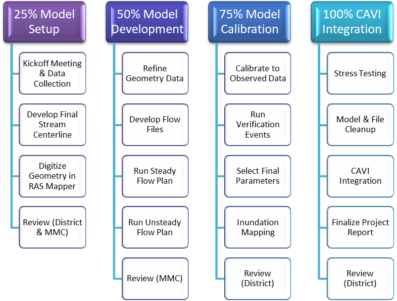
Figure 5-1. HEC-RAS Modeling Workflow
5.2.1 Model Setup (25 Percent Milestone)
The first step in developing a HEC-RAS model is the creation of a geometry file that includes all necessary features to accurately compute hydraulic profiles within the basin, such as cross sections, bridges, lateral structure, storage areas, and 2D flow areas. If an existing HEC-RAS model is deemed suitable to use, the geometric features can be imported into the CWMS HEC-RAS model. If necessary, the modeler can use RAS Mapper to generate any new features or supplement those from an existing model with the geospatial framework. The deliverable for the 25 percent milestone consists of an initial HEC-RAS geometry that covers the required footprint within the watershed.
5.2.2 Model Development (50 Percent Milestone)
Once the geometry layout is established, the HEC-RAS modeler will continue to incorporate data into the geometry to complete the final geometry setup. Development of the other files needed to run the model, including flow and plan files, is also completed at this time. The model will include major boundary conditions, hydraulically-significant structures, both steady and unsteady flow scenarios, and the expected final model configuration. The deliverable for the 50 percent milestone consists of an uncalibrated HEC-RAS model that successfully runs without any major errors.
5.2.3 Model Calibration and Verification (75 Percent Milestone)
The next step in HEC-RAS model development is the calibration of the model to historic events using stream gage records. Additional historical events are simulated, and model results are compared to stream gage records without any model parameter adjustment to validate the model geometry. The deliverable for the 75 percent milestone consists of a calibrated and verified HEC-RAS model.
5.2.4 Control and Visualization Interface Integration (100 Percent Milestone)
Once the HEC-RAS model is calibrated and validated, the model is stress tested to ensure it will function properly for a wide range of flow regimes. The model is then cleaned up and integrated into the CAVI. The deliverables for the 100 percent milestone are the final HEC-RAS model that has been integrated into the CAVI watershed and the completed HEC-RAS section of the project report.
5.3 Model Setup (25 Percent Milestone)
The HEC-RAS modeler begins model development by creating the initial geometry layout. If existing HEC-RAS models are provided by the district, geometric features such as cross sections or storage areas could be imported into the CWMS HEC-RAS model. Other geometry layers may be digitized within RAS Mapper and refined in the Geometric Data Editor to complete the geometry setup. The deliverable for this milestone is a HEC-RAS geometry that includes all necessary features for the model (cross sections, storage areas, 2D flow areas, bridges, inline structures, etc.).
5.3.1 Pre-Existing Model Data Assessment
Existing models of sufficient quality can be used during the development of the CWMS HEC-RAS model. Existing models are assessed to ensure the geometry and hydraulic features are accurate and represent the current condition of the stream system. Of particular interest are inline structures, bridges and culverts, bathymetric data, and overbank properties. Uncalibrated models or those of questionable data should not be used for CWMS HEC-RAS model development. A consistency check of the existing model is needed to ensure the models are in the correct vertical datum and horizontal projection. Existing models originally developed in a different projection may need to have the geometry re-projected into the standard MMC projection (Albers Equal Area). The HEC-RAS modeler can use the conversion tools within the model to accomplish this task.
5.3.2 General Methodology
Standard pre-model GIS data is used as the base for building the HEC-RAS model when a suitable existing model is not available. DEMs and all shapefiles are developed and delivered by the mapping team in accordance with specifications set in Appendix 4.1.1. RAS Mapper is used to develop a preliminary model framework using pre-model GIS data. For specifics on how to use RAS Mapper, refer to the HEC-RAS User’s Manual. Typical model data needed may include, but not be limited to, the following:
- Stream centerlines
- Cross sections
- Flow paths
- Bank lines
- Lateral structures
- Levees
- Storage areas
- Storage area connections
- Two-Dimensional (2-D) flow areas, refinement regions, and breaklines
- Inline structures
- Ineffective flow areas
- Blocked obstructions
5.3.3 Geometric Data Development
During the geometric data development, the modeler will define important features of the HEC-RAS model, including stream centerlines, cross sections, bridges, lateral structures, storage areas, and 2D flow areas. Other model data, as listed in Section 5.3.3.8, may be digitized using RAS Mapper at the discretion of the modeler.
5.3.3.1 Terrain
The HEC-RAS modeler will create a new terrain in RAS Mapper using DEMs provided by the GIS team member and/or district. Multiple datasets with varying cell size can be used to create a terrain file in RAS Mapper. LiDAR data can be combined with coarse datasets to cover the entire footprint needed for inundation mapping directly in RAS Mapper, as the software stitches the data together when the terrain is created by the modeler. Once the geometry has been finalized, the channel data should be exported from the cross sections and used to create a final terrain dataset that includes the channel bathymetry. Refer to Section 5.4.1.8 for further instructions.
5.3.3.2 Stream Centerlines
The stream centerline used is the centerline agreed upon by the PDT in accordance with Section 1.7.3 of this technical manual. If refinement of the agreed upon centerline is necessary during HEC-RAS model development, the entire PDT is notified immediately so the necessary changes can be made to the other watershed models.
5.3.3.3 Cross Sections
Cross sections may be copied from an existing HEC-RAS model. Cross sections shall be wide enough to contain flows from dam breach scenarios. In general, the use of interpolated cross sections is not recommended; additional cross sections can be created using RAS Mapper if needed. Interpolation is acceptable in areas where flow is rapidly varying but the shape of the land surface is consistent. Additionally, if an existing model does not cover the footprint needed for the CWMS HEC-RAS modeling effort, cross sections can be added using RAS Mapper. The use of river miles or feet when stationing cross sections is discussed during the kickoff meeting, however it is recommended that the model use river miles.
5.3.3.4 Bridges
Critical bridges and culverts are modeled as part of this effort as data are available. If bridge or culvert data is not available, it is up to the discretion of the CWMS team lead and district to decide whether the structures should be included in the model. The decision should be well documented in the HEC-RAS section of the project report. Cross sections representing the constriction caused by the bridge abutments should be included if the modeler decides not to include the structure as a bridge in the model geometry.
5.3.3.5 Levees
Levee data are available in the NLD and are provided as part of the pre-model GIS data. Levees are to be included in all MMC models. If additional data is needed, all NLD data requests are met by the GIS team member. Levees not included in the NLD, but visible on the DEM, should also be included in the model.
5.3.3.6 Storage Areas
Floodplain and backwater storage is an important aspect of hydraulic analysis and flood routing to account for flow volume and hydrograph attenuation. Storage can be modeled in HEC-RAS by adding storage areas connected with lateral structures, extending cross sections up tributaries, or by adding additional reaches for significant tributaries. Each of these options has explicit hydraulic consequences and should be well understood by the modeler before choosing which method is most appropriate.
Some of the conditions that require modeling a tributary as a separate reach include:
- Tributaries containing a USACE-operated dam
- Significant population area(s) on the tributary
- NLD levees along the tributary
Coordination with the HEC-FIA modeler may be needed to ensure consequences are being adequately computed. This is especially true in locations where the storage area runs parallel to the river centerline in heavily populated areas.
NOTE
For consequence analysis, the HEC-FIA program calculates consequences differently when modeling backwater storage in HEC-RAS as storage areas versus modeling backwater storage using cross sections with ineffective areas. When there is significant population in a backwater storage area, it should be modeled using a storage area, a 2D flow area, or a separate river reach.
5.3.3.7 Storage Area/2D Area Connections
Storage area (SA)/2D area connections are hydraulic features used to link two storage areas. SA/2D area connections can consist of a weir, culverts and a weir, gated spillways and a weir, or a linear routing option. If connected storage areas exist in the river system, the connection method selected should be appropriate for the system being modeled.
5.3.3.8 Inline Structures
Inline structures predicted to influence local hydraulics within the HEC-RAS modeling domain should be included in the HEC-RAS geometry. The modeler works with the district to identify all inline structures (such as small dams) necessary to include within the HEC-RAS model.
5.3.3.9 2D Flow Areas
HEC-RAS gives the modeler the option to use one-dimensional (1D) storage areas or 2D flow areas. It is up to the team and the district to decide what method is appropriate to use given the characteristics of flow in the system and goals for the model. If levee breaching or overtopping is of interest, the HEC-RAS modeler may choose to use 2D flow areas behind the levee to better represent those conditions during a real-time flood event. The modeler may also choose to use 2D flow areas when a standard 1D model geometry setup will not suffice.
5.3.3.10 Other Geometric Features
The HEC-RAS modeler can decide to use RAS Mapper to define other geometric features if they choose, such as bank lines, ineffective areas, blocked obstructions, and Manning’s “n” value regions. These features can be included later during the HEC-RAS model geometry refinement if not included during the initial geometry development.
5.3.4 Documentation of Model Setup
Once the model setup using RAS Mapper is complete, the modeler should obtain the HEC-RAS section of the project report template and complete all relevant sections. Any assumptions or issues concerning the initial setup of the model should be documented at this time.
5.3.5 Interim Model Review (25 Percent Milestone Review)
Once the initial HEC-RAS geometry has been created, the modeler completes the 25 percent portion of the MMC HEC-RAS review checklist. The modeler uploads a zipped copy of the preliminary model, the draft HEC-RAS section of the project report, and the completed review checklist to the corresponding milestone folder on ProjectWise and submits the package for interim review. The files are also submitted for a consistency review conducted by the MMC modeling team.
5.3.6 Incorporating Review Comments
Any comments received from the 25 percent milestone review are addressed and incorporated into the HEC-RAS model and the draft HEC-RAS section of the project report as needed.
5.4 Model Development (50 Percent Milestone)
The next phase of HEC-RAS model development includes refining the geometry data within the model, developing steady and unsteady flow and plan files, and executing the plans to ensure that the model can run and is ready for calibration in the next phase of the project. The deliverable for this milestone is an uncalibrated HEC-RAS model that incorporates initial HEC-HMS outputs and runs without any major errors.
5.4.1 Geometric Data Refinement
Once the initial geometry layout has been reviewed and approved, the HEC-RAS modeler can begin to refine the geometry data within the model.
5.4.1.1 Cross Section Bathymetry
Unless the terrain included bathymetric data, the modeler will have to manually input station/elevation data into the model to accurately depict channel geometry. Sources of bathymetry data include:
- Channel Survey Data
- Existing HEC-RAS models
- FEMA Floodplain HEC-RAS models
If bathymetry data is not available, the modeler should assume an average depth and generic shape to cut into the cross sections. Any assumptions or sources of data should be documented in the model and project report.
5.4.1.2 Manning’s “n” Values
The selection of “n” values is left to the judgment of the HEC-RAS modeler. Horizontal and vertical variation in “n” values should be used with discretion, if needed. The modeler can use existing HEC-RAS models of the river as reference when setting initial “n” values. Land cover datasets or aerial imagery are also valuable references that should be used by the HEC-RAS modeler if there are no existing HEC-RAS models available.
5.4.1.3 Bridge Data
Bridge data may be obtained from several sources, including existing HEC-RAS models or construction drawings. If data is not available in a timely manner, the structure geometry can be estimated using aerial photography (such as Google Earth). If the bridge has piers, those should be included in the model geometry, even if the modeler must estimate the size and location of the piers. Any sources of data or assumptions should be included in the HEC-RAS model and in the project report.
NOTE
Bridges with multiple opening analysis turned on can slow runtimes down considerably. If runtimes are not reasonable for daily operations, consider modifying the geometry (turning off multiple opening analysis) to reduce runtimes.
5.4.1.4 Lateral Structures
Station/Elevation data for lateral structures that was pulled from the terrain can be used if the terrain is the best source of data. This may be true for features such as road or railroad embankments, natural high ground, or levees not within the NLD.
For lateral structures representing levees within the NLD, the station/elevation data extracted from the terrain should be replaced with the surveyed data from the NLD. If the data from the NLD does not cover the full length of the connection, the HEC-RAS modeler should smooth the transition between the NLD data and the data pulled from the underlying terrain. Please refer to Appendix 4.1.8 for further guidance on how to include NLD survey data into the HEC-RAS model.
The data source should be documented within the model and in the project report.
5.4.1.5 Inline Structures
If an inline structure has gated outlets, the modeler should choose the appropriate gate methodology to use within the HEC-RAS model. Rating curves or gate types (sluice, radial, or overflow) can be used. Gate locations in the model should approximately correspond to their physical location in the structure. Gate operations (opening and closing) within the HEC-RAS model should correspond to the operations set forth in the WCM for the structure. Elevation control or rules are the preferred method of operation. The modeler should pay careful attention to the vertical datums used within the WCMs and convert to the MMC standard if needed. For additional guidance on gated structures, refer to the HEC-RAS User’s Manual.
5.4.1.6 Storage Areas
The names of HEC-RAS storage areas are agreed upon by the modeler and the district staff. HEC-RAS storage areas can be named as river miles in accordance with their location along the river reach. Other options are names that represent a levee district, population center, tributary, or other notable feature located within the storage area. One-dimensional storage area elevation/storage curves should be pulled from the terrain data used to develop the model inputs. Any edits to the curves should only be made to improve model stability.
5.4.1.7 2D Flow Areas
If using 2D flow areas, the modeler should begin to develop and edit the mesh for each flow area. This includes adding breaklines, refinement regions, and SA/2D connections as necessary. The modeler should also refine the default Manning’s “n” value for the 2D flow areas by associating a land cover dataset, such as the most recent National Land Cover Dataset (NLCD), with the 2D flow area. The modeler should also assign appropriate Manning’s “n” values to each land cover type. For more information on typical Manning’s “n” values to use for the NLCD land cover types, please refer to the HEC-RAS 2D User’s Manual.
5.4.1.8 Storage Area/2D Flow Area Connections
For any storage area/2D area connections that represent levees within the NLD, the station/elevation data extracted from the terrain should be replaced with the surveyed data from the NLD. If the data from the NLD does not cover the full length of the connection, the HEC-RAS modeler should smooth the transition between the NLD data and the data pulled from the underlying terrain. Please refer to Appendix 4.1.8 for further guidance on how to include NLD survey data into the HEC-RAS model.
Other storage area connections should rely on station/elevation data extracted from the terrain.
The data sources should be documented within the model and in the project report.
5.4.1.9 Ineffective Flow Areas and Blocked Obstructions
Ineffective flow areas are used to properly account for flood plain storage in locations that do not actively convey flow. The modeler should set the initial extents of the ineffective areas based on judgment and then further refine during calibration, if necessary.
The use of blocked obstructions is acceptable for use in MMC models when an obstruction exists at a cross section.
5.4.1.10 Final Terrain Dataset
Once the HEC-RAS modeler finalizes the geometry, the channel data should be exported and used to create a final terrain dataset that includes channel bathymetry. If bathymetric data was included in the original terrain data, this step can be skipped. Refer to the HEC-RAS User’s Manual for further instructions.
5.4.2 Steady Flow Model Development
An HEC-RAS flow file is required to specify inflows and boundary conditions for the river system. For the initial model setup, a steady flow file is developed using flows and boundary conditions representative of the range of flows anticipated during real-time operations.
For models with 2D flow areas, this requirement can be skipped as the models will not run using steady flow boundary conditions.
5.4.2.1 Steady Flow Data
At a minimum, for all stream segments, 15–20 flow rates are entered into the steady state flow file that bracket the extreme flows expected during implementation. Running the model with these extreme flow conditions aids in diagnosing model geometry and stability problems. Flow rates should range from low flows to extremely high flows. These flow rates do not have to correspond to a frequency of occurrence or exceedance; they only need to encapsulate the possible range of flows that could be encountered during implementation.
5.4.2.2 Downstream Boundary Conditions
Downstream boundary conditions are set to appropriately represent conditions at the downstream extent of the model. Generally, normal depth is used for models with typical riverine characteristics at the downstream boundary. If the downstream boundary is a large body of water (i.e., ocean), other boundary conditions (tide signals, prevailing water surface elevations, etc.) are used. If known stage or flow is used as a boundary condition, the modeler coordinates with the district CWMS system administrator to ensure forecasted data is available. This forecasted data could come from the NWS, USACE, or other entities.
5.4.2.3 Upstream Boundary Conditions
Upstream boundary conditions are required for steady flow models that experience supercritical flow during the simulation. In many cases, increasing the Manning’s “n” values in reaches with steep slopes will prevent the model from going supercritical. Supercritical flow is rare in natural systems, even for steep streams, but if the HEC-RAS modeler believes this is the case, the model should be executed using a mixed flow regime. The upstream boundary condition for a mixed flow model can be an inflow hydrograph, a stage hydrograph, stage and flow hydrograph, or a storage area reservoir. The upstream boundary condition selected is based on information available to the modeler and should be appropriate for the river system being modeled.
5.4.2.4 Developing the Steady Flow Plan and Running the Model
An HEC-RAS steady flow plan file is used to define the geometry and flow files used in each analysis. In addition, the plan file sets the computational settings and model output options for each modeled scenario. A steady flow plan is created that uses the geometry developed for the 25 percent milestone and the steady flow file discussed in Section 5.4.2.1, with default computational settings. By default, all simulations are executed using a subcritical flow regime. However, some stream systems require the use of a mixed flow regime. The modeler should discuss these options with the district.
5.4.2.5 Evaluating and Modifying the Model to Improve Results
Once the steady flow plan has executed successfully, the modeler examines the results to identify inconsistencies, errors, or shortcomings in the model. Cross section spacing is reviewed and additional sections are inserted to improve model results at this time (if necessary). During the initial steady flow phase of this effort, model stability is the primary goal; calibration and refinement of the model are conducted during the next phase.
5.4.3 Unsteady Flow Model Development
Every scenario modeled will have a separate HEC-RAS plan file. The plan file contains data designating the geometry and flow files associated with the model scenario. The plan file also contains information on the simulation time window and computational settings. Levee and dam breach parameters are also stored within the plan file. Scenarios that might be incorporated into the final CWMS model are determined by the circumstances and characteristics of the river being modeled, and a new plan file is developed for each scenario. Some common scenarios might include:
- Existing conditions
- Levee breaching
- Modified channel
5.4.3.1 Downstream Boundary Conditions
Downstream boundary conditions are set to appropriately model conditions at the downstream extent of the study. Generally, normal depth is used for models with typical riverine characteristics at the downstream boundary. When using the normal depth boundary condition, the study reach should extend far enough downstream such that water surface errors will not affect the results within the study reach. Other boundary conditions may be used if necessary. If known stage or flow is used as a boundary condition, the HEC-RAS modeler should check with the district CWMS system administrator to ensure forecasted data is available for the time series. This forecast data could come from the NWS, USACE, or other entities.
5.4.3.2 Upstream Boundary Conditions
The upstream boundary conditions for unsteady runs should be output from either the HEC-HMS or HEC-ResSim model, depending on the configuration of the HEC-RAS model. The HEC-RAS modeler should coordinate with both the HEC-HMS and HEC-ResSim modelers to determine which outputs are to be linked within the HEC-RAS model at the upstream end of each river reach.
Minimum flowrates may be necessary to ensure the HEC-RAS model is stable during all potential flow scenarios. The HEC-RAS modeler should include minimum flowrates for each boundary condition, if needed, to keep the model stable during the entire forecast run. The modeler should keep those values as low as possible to prevent unrealistic conditions within the model (minimum flows should be less than channel capacity flows, for example).
5.4.3.3 Lateral Inflow Boundary Conditions
Output hydrographs from the HEC-HMS model sub-basins and reaches are critical for proper computation of hydraulic profiles within the HEC-RAS model. The HEC-HMS modeler should provide a DSS file of the output from an HEC-HMS model run to the HEC-RAS modeler. The HEC-RAS modeler should work with the HEC-HMS modeler to identify which flow files to use as inputs for the HEC-RAS model and determine which cross sections to tie the inflows to. Lateral inflows are placed at a cross section as a lateral inflow hydrograph and not as a uniform lateral inflow, as this can cause the HEC-RAS model to double account for routing.
5.4.3.4 Simulation Time Window
The simulation time window is set to match the time window of the data obtained from HEC-ResSim and HEC-HMS. Simulations using historical data must begin on the date for which data is available to allow the program to run. Simulations should run until the peak of the flood wave has been routed through the model extents and water surface elevations at the most downstream cross section have begun to recede.
5.4.3.5 Computational Time Step
The computation interval is used only in unsteady calculations and is one of the most important parameters entered into the model. The computation interval should be small enough to accurately describe the rise and fall of the hydrograph being routed. A general rule of thumb is to use a computation interval that is equal to or less than the time of rise of the hydrograph divided by 20. This estimation gives an upper bound of the time step. A primary method of estimating the computation interval is by applying a numerical accuracy criterion called the Courant condition. This criterion looks at cross section spacing and flood wave velocity. The basic premise is that the computation interval should be equal to or less than the time it takes water to travel from one cross section to the next. This consideration is true for 2D flow areas as well. If the model is a combined 1D/2D model, the modeler will need to use the Time Slicing option for the 2D flow areas to reduce the time step for individual 2D flow areas.
5.4.3.6 Computational Settings and Options
Computational settings should be left at their default unless there is justification beyond improving model stability for changing them.
5.4.3.7 Running the Model and Evaluating Results
The HEC-RAS model should compute all scenarios with minimal computational error. Instability in unsteady HEC-RAS model runs is expected during initial simulation. It is likely to take several iterations before instabilities are fully addressed in the model. A high-flow event and a low-flow event are run to test model stability. The HEC-RAS model is further adjusted so that computational error is minimized.
For models with 2D flow areas, the modeler should review the volume accounting check and determine if the errors are acceptable (volume differences less than 2 percent are considered acceptable). If the volume errors are considered to be unacceptable, the modeler should review the Computation Log File to determine which 2D flow areas are experiencing the largest errors and adjust the model as needed to correct the issues. Please refer to the HEC-RAS 2D User’s Manual for more information.
5.4.3.8 Modifying the Model to Improve Results
Changes in flow or stage at the beginning of the model run are common and typically caused by differences in initial flow conditions and cumulative inflows upstream of a particular location. The use of a warm-up period may provide additional model stability at the start of the simulation. HEC-RAS computes initial flows and storage area elevations if the table is left blank, however this may not produce reasonable results for all simulations. The modeler should investigate the initial conditions to ensure model stability and accuracy.
The following model output checks should be performed to ensure the model is accurately computing flows and water surface elevations at all cross sections:
- All model output profiles are reviewed for water surface spikes and energy grade spikes
- The profile output table is reviewed for sudden changes in top width
- Simulations are run until the peak of the hydrograph has been routed downstream through the entire model extent
- The volume accounting errors are reviewed for models with 2D flow areas
5.4.4 Documentation of Model Development
Once the initial HEC-RAS model development is complete, the modeler should obtain the draft HEC-RAS section of the project report completed for the 25 percent milestone review and update the report as necessary. Any assumptions or issues concerning the initial development of the HEC-RAS model should be documented at this time.
5.4.5 Interim Model Review (50 Percent Milestone Review)
Once the initial HEC-RAS model development is complete, the modeler completes the 50 percent portion of the MMC HEC-RAS review checklist. The modeler uploads a zipped copy of the interim model, the draft HEC-RAS section of the project report, and the completed review checklist to the corresponding milestone folder on ProjectWise and submits the package for review.
5.4.6 Incorporating Review Comments
Any comments received from the 50 percent milestone review are addressed and incorporated into the HEC-RAS model and the draft HEC-RAS section of the project report as needed.
5.5 Model Calibration and Verification (75 Percent Milestone)
Calibration is a critical step in the development of the HEC-RAS model. The modeler should work in conjunction with the other modelers on the team to produce a calibrated HEC-RAS model useful for real-time forecasting.
The deliverable for this milestone is a calibrated and verified HEC-RAS model that incorporates HEC-HMS and HEC-ResSim outputs.
5.5.1 Non-Damaging Flow Run
Before starting model calibration, the HEC-RAS modeler will run a non-damaging flow through the model to provide output for the calibration of the HEC-FIA model. Often, this information is listed in WCMs as channel capacity, but more information for flood stage or action stage may be available from the NWS River Forecast Center website for each gage location. If needed, the HEC-RAS modeler may choose to adjust Manning’s “n” values for the channel. The output from the non-damaging HEC-RAS plan should be provided to the HEC-FIA modeler for calibration of the HEC-FIA model.
5.5.2 Calibrating the Model to Historic Events
The modeler should create separate plans for each historic event that includes the appropriate geometry and flow files. The HEC-RAS modeler then calibrates the model to observed flows and water surface elevations and adjusting the model parameters iteratively so model output closely matches the observed data. This may involve adjustment of model parameters such as roughness coefficients, cross section spacing, or ineffective areas.
5.5.2.1 Calibrating to Gage Data and High Water Marks
Measured stage data is often the most accurate hydraulic measurement available. Measured stage data is normally well within ±1.0 feet accuracy, but error can be introduced for various reasons (such as a gage float getting stuck). These issues should be considered when evaluating the accuracy of gage data.
If gage data is available in the study reach, it should be used to calibrate the HEC-RAS model. When using elevation data, it is important to know what vertical datum it was collected in, as the modeler may need to adjust the elevations to NAVD 88 datum for calibration of the model. The district’s CWMS database should be the main source of gage data, but data may also be obtained from the USGS or NWS gage sites.
The modeler should be cautious when using measured stage/elevation data to calibrate the HEC-RAS model. It is important to understand where that data was collected, as it will impact the calibration effort. If the data was collected within the channel, such as by a stream gage, then the modeler should be calibrating the observed data to the hydraulic grade line (water surface elevation) within the HEC-RAS model. However, if the data was collected in the overbanks, such as high water marks, then the modeler should be calibrating the observed data to the energy grade line within the HEC-RAS model.
Calibration of the HEC-RAS model is an iterative process. Initial outflows from HEC-HMS calibration runs should be provided and used as inputs to the HEC-RAS model. The HEC-RAS modeler should then calibrate the model to historic gage data and provide updated routing parameters to the HEC-HMS modeler if they change significantly. This process should be repeated until the HEC-HMS and HEC-RAS modelers are happy with the calibration results. Refer to Section 3.5.1 for more information.
The HEC-RAS modeler should be cautious when calibrating. They should not use unrealistic Manning’s “n” values just to achieve a target stage, as this may have a negative impact on the timing of the hydrograph and may result in inaccurate stages for other events. If a calibration target is not achievable with realistic “n” values, other parameters in the model should be adjusted. Discrepancies may also arise from a lack of quality cross section and terrain data. If the HEC-RAS model has cross sections cut from a 10-meter DEM or cross sections with estimated bathymetry, calibration targets should be adjusted.
The modeler should also consider what occurred during the flood that may impact gage data they are using for calibration of the HEC-RAS model. Flood fighting efforts may have prevented a levee from overtopping. Ice jams or debris on bridges may have caused stream gages to record abnormally high stages. Channel bathymetry may have changed significantly since the calibration event. All these factors should be considered when choosing calibration events and when deciding when the model is “calibrated”. For additional discussion on model calibration, refer to the HEC-RAS User’s Manual.
The HEC-RAS model is typically calibrated to high flow events, but low flow events should also be run to ensure model stability. Calibrating to low flow events can help the modeler determine if the channel portion of the cross sections are accurate (Manning’s “n” values, bathymetry, bank stations, etc.).
The modeler is responsible for determining the minimum flow rate for each stream within the HEC-RAS modeling domain. This helps maintain model stability throughout the length of each simulation. These minimum flow rates are included in the unsteady flow file and used for all future simulations, including real-time forecasts.
5.5.3 Running Verification Events
Once the model has been calibrated to historic events, the adequacy of the HEC-RAS model is verified by running other historic events not used for calibration. If further adjustment to model parameters is necessary, the modeler adjusts model parameters and re-runs all calibration and verification events. This may be an iterative process until the modeler is satisfied with the model results.
5.5.4 Selection of Final Model Parameters
The final HEC-RAS model parameters are set once the desired calibration and verification targets are met. If multiple calibration events were run, the HEC-RAS modeler should average the model parameters from each plan to determine the final set of parameters. This process should be documented in the project report.
5.5.5 Performing Inundation Mapping of Desired Events
The HEC-RAS modeler uses RAS Mapper to generate inundation depth grids for the calibration runs. At a minimum, depth grids for a high-flow event and a low-flow event (within channel discharge, aka non-damaging scenario) are generated and shared with the HEC-FIA modeler for calibration of the HEC-FIA model.
The modeler should review the inundation extents to determine if the edge lines need to be adjusted. The edge lines can be edited between the endpoints of the cross sections to ensure inundation mapping is correct. For example, there can be small gaps between the 1D cross sections and a lateral structure that connects to a storage area or 2D flow area. The modeler can edit the edge lines in RAS Mapper to remove the gaps and ensure proper mapping along the entire reach.
5.5.6 Documentation of Model Calibration and Verification
Once the calibration and verification of the HEC-RAS model is complete, the modeler should obtain the draft HEC-RAS section of the project report completed for the 50 percent milestone review and update the report as necessary. Any assumptions or issues concerning the calibration and verification of the HEC-RAS model should be documented at this time.
5.5.7 Interim Model Review (75 Percent Milestone Review)
Once the calibration of the HEC-RAS model is complete, the modeler completes the 75 percent portion of the MMC HEC-RAS review checklist. The modeler uploads a zipped copy of the calibrated model, the draft HEC-RAS section of the project report, and the completed review checklist to the corresponding milestone folder on ProjectWise and submits the package for interim review.
5.5.8 Incorporating Review Comments
Any comments received from the 75 percent milestone review are addressed and incorporated into the HEC-RAS model and the draft HEC-RAS section of the project report as needed.
5.6 Control and Visualization Interface Integration (100 Percent Milestone)
Once the HEC-RAS model has been calibrated, it should be stress tested to ensure it is sufficient for the entire range of events that might be expected. This may include extreme low flow events, extreme flood events, or dam/levee breach scenarios.
The deliverable for this milestone is the final HEC-RAS model integrated into the CAVI watershed and the completed HEC-RAS section of the project report.
5.6.1 Stress Testing Using Extreme Events
The HEC-RAS modeler should stress test the model by running events that are of a higher and lower magnitude than used in the model calibration and verification process. Observed data from historic events smaller or larger than those used in the calibration and verification process may not be available, but these events can by created by scaling flows of the historic events available. Hydrographs from hypothetical events such as a PMF or dam failure may also be used. The HEC-RAS modeler should be evaluating the model for reasonableness of results and model robustness at this point, rather than verifying the accuracy of results.
5.6.2 Sensitivity Analysis
Model sensitivity is an important part of understanding the accuracy and uncertainty of a model. There are two types of sensitivity analysis that should be performed: numerical sensitivity and physical parameter sensitivity. These efforts focus primarily on physical parameter sensitivity.
5.6.2.1 Manning’s “n” Values
The modeler estimates a realistic range for “n” values used in the model. For example, if an “n” value of 0.035 is estimated for the river channel, a realistic range of values might be 0.03 to 0.045. The modeler runs the lower “n” value and the higher “n” value to evaluate the final model’s sensitivity to this parameter.
5.6.2.2 Hydraulic Structure Gate Changes
The rate of gate opening can affect the magnitude of flows as well as upstream and downstream water surface elevations. Initial gate opening rates are based on documented rates from WCMs or other guidance, but a range of reasonable values for these rates are also evaluated to determine the model’s sensitivity to this parameter.
5.6.2.3 Initial Conditions
Different boundary conditions may have a significant effect on the model. Like the “n” value and gate opening analysis, a reasonable range for initial and boundary conditions should be evaluated. If normal depth is used as the downstream boundary condition, the slope should be evaluated for values higher and lower than those used in the calibration effort. Other parameters, like initial reservoir elevation or tributary inflow, are evaluated for a range of values as well. These parameters should be evaluated independently, changing only one for each model run, to evaluate the individual effect on model sensitivity.
5.6.3 Creating a Steady Flow Backup Plan
A steady flow plan should always be included in the CWMS CAVI so it can be used as a backup if the unsteady flow model goes unstable, as steady flow models are generally more stable than their unsteady counterpart. The HEC-RAS modeler will create a steady flow forecast alternative that is available for use in real-time forecasting. The only time that this step may be skipped is if the HEC-RAS model is setup in such a way that requires the use of an unsteady flow plan, such as the use of 2D flow areas within the model.
5.6.4 Model Cleanup
Before transferring the model to the CAVI modeler, the HEC-RAS modeler uploads a complete copy (zipped) of the model including all calibration and validation runs to ProjectWise. The HEC-RAS model for incorporation into the CAVI watershed should only contain the final calibrated geometry, flow, and plan files. This includes a steady flow plan, an unsteady flow plan, and any necessary model alternative files (e.g., plans/files for alternative analysis like levee breaching, etc.). All other HEC-RAS files, such as previous geometry iterations, calibration plans, and extraneous flow files should be deleted from the model directory.
HEC-RAS contains an archiving tool that will allow the modeler to choose which files and plans to include in an archived (zipped) copy of the model. Please refer to the HEC-RAS User’s Manual for more information.
5.6.5 Control and Visualization Interface Integration
The HEC-RAS modeler will assist the CAVI modeler in importing the HEC-RAS model into the CAVI. Once the HEC-RAS model directory has been cleaned up, the HEC-RAS modeler works with the CAVI modeler to import the HEC-RAS model into the CAVI. See Section 7.4.1 for further instructions.
5.6.6 Documentation of Final Model Development
The section of the project report covering the HEC-RAS model development should be almost complete at this point, as it builds on the draft report written for the previous project milestones. Any additional information or items of interest not previously discussed are added to the report as needed. Documentation of any unresolved issues that may impact real-time operations or model results is important.
5.6.7 Final Model Review (100 Percent Milestone Review)
Once the HEC-RAS model has been finalized, the modeler completes the 100 percent HEC-RAS portion of the MMC review checklist. The modeler uploads a zipped copy of the final model, the final HEC-RAS section of the project report, and the completed review checklist to the corresponding milestone folder on ProjectWise and submits the package for final review.
5.6.8 Incorporating Review Comments
Any comments received from the 100 percent milestone review are addressed and incorporated into the HEC-RAS model and the final HEC-RAS section of the project report as needed.
5.6.9 Testing the Model within the Control and Visualization Interface
The HEC-RAS modeler and CAVI modeler work together to ensure the HEC-RAS model is working properly within the CWMS CAVI environment. The HEC-RAS modeler is responsible for reviewing model results computed in the CAVI and verifying model calibration.
5.6.10 Final Model Storage
As described in Section 5.6.4, the version of the HEC-RAS model that includes all calibration and validation runs and associated data should be zipped and uploaded to ProjectWise. The cleaned-up version of the HEC-RAS model, for import into the CAVI watershed, should also be zipped and uploaded to ProjectWise. The files should be named so that it is easy to distinguish between the two versions. It is the responsibility of the modeler to upload all files relating to the development of the HEC-RAS model for final storage on ProjectWise at the end of the project.
5.7 Reference Material
The following sources may be helpful to team members developing the HEC-RAS model. Team members can locate these sources by following the citation information found in Section 12.
- EM 1110-2-1416, “River Hydraulics”
- HEC-RAS User’s Manual
- HEC-RAS 2D User’s Manual
- HEC-RAS Hydraulic Reference Manual
- HEC-RAS Applications Guide
- CWMS User’s Manual
- PROSPECT Course Materials
- Steady Flow Hydraulics with HEC-RAS
- Advanced Steady Flow Analysis with HEC-RAS
- Unsteady Flow Analysis with HEC-RAS
- Advanced 1D/2D Modeling with HEC-RAS
- H&H for Dam Safety Study
Section 6 - HEC-FIA Model Development
This section describes the purpose, requirements, products, and standards for HEC-FIA model development for CWMS implementation. This section also describes basic processes to follow when developing HEC-FIA models for use within CWMS. This section is not intended to provide a step-by-step guide for this process and is written assuming the reader has a moderate understanding of HEC-FIA.
6.1 Modeling Objective
The HEC-FIA modeler’s objective is to develop a HEC-FIA model capable of computing structural damages for use within the CWMS framework. The model should be able to estimate economic damages during a real-time flood event and compute annual flood damage reductions based on the operations within the basin for the previous year. Agricultural damage computations should be included if the district identifies the need for it.
6.2 Modeling Milestones
The HEC-FIA modeler prepares intermediate deliverables and provides them for review at key production points of the model development. A brief description of the milestones is provided in Sections 6.2.1-6.2.4. In addition, Figure 6-1 provides a workflow diagram of the process.
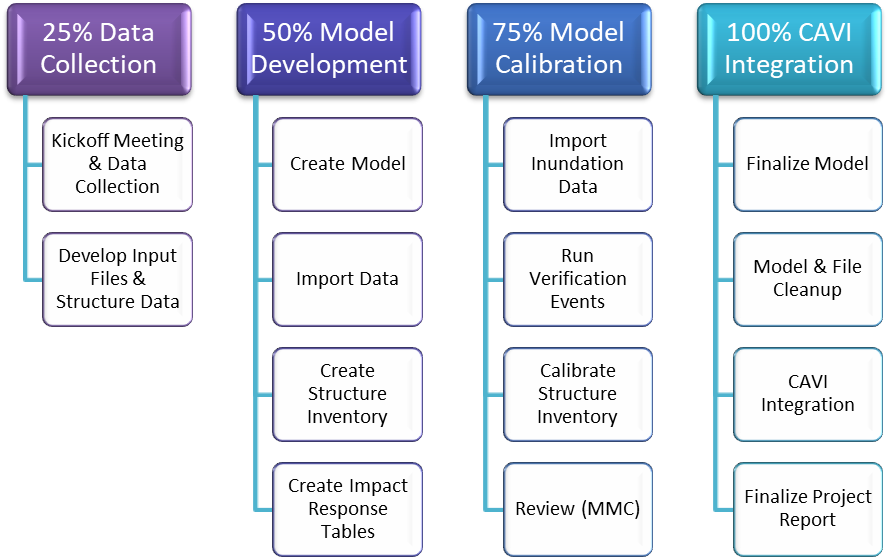
Figure 6-1. HEC-FIA Modeling Workflow
6.2.1 Data Collection (25 Percent Milestone)
After the kickoff meeting, the HEC-FIA modeler begins collecting data, such as structure information and other GIS files needed for model development. If parcel data or previously modified inventories are available, the modeler prepares those files for the HEC-FIA model during this time.
The deliverable for the 25 percent milestone is a collection of datasets that will be used during subsequent milestones to develop the HEC-FIA model.
6.2.2 Model Development (50 Percent Milestone)
The HEC-FIA model is created using the data collected in the previous milestone. The model should be ready for HEC-RAS outputs at this point. The structure inventory may be a basic, un-modified inventory that is further improved during the calibration phase.
The deliverable for the 50 percent milestone is an HEC-FIA model that includes terrain data, impact areas, river centerlines, cross sections, and a structure inventory.
6.2.3 Model Calibration and Verification (75 Percent Milestone)
HEC-RAS output files for several flood events are used in the HEC-FIA model to calibrate the structure inventory based on the results from the model runs.
The deliverable for the 75 percent milestone is an HEC-FIA model that has successfully computed damages for several calibration events.
6.2.4 Control and Visualization Interface Integration (100 Percent Milestone)
Final adjustments are made to the HEC-FIA model as needed to satisfy any review comments. The model is imported into the CAVI watershed and tested to ensure it is functioning properly.
The deliverables for the 100 percent milestone are the final HEC-FIA model that has been integrated into the CAVI watershed and the completed HEC-FIA section of the project report.
6.3 Data Collection (25 Percent Milestone)
The initial phase of development for the HEC-FIA model is a data collection effort. The HEC-FIA modeler will coordinate with the district to ensure all existing models and sources of data needed for the model are aggregated.
The deliverable for this milestone is a collection of existing HEC-FIA model(s), structure inventories, and other GIS datasets that will be used to build the CWMS HEC-FIA model.
6.3.1 Kickoff Meeting
The kickoff meeting is an important event in the data collection for HEC-FIA modeling. Many of the model inputs are coordinated with district personnel, and the kickoff meeting is the best time to accomplish this. The kickoff meeting is also when the modeling scope will be determined. Important issues to discuss during the kickoff meeting include:
- Existing models and data
- Model setup and scope
- CCPs and holdout areas
- Agriculture damage computations
- Levee modeling strategies
- Critical infrastructure
- Areas of concern that control reservoir operations
- Layout of CCP and holdout areas for Flood Damage Reduction computations
6.3.1.1 Existing Models and Data
The HEC-FIA modeler should obtain any existing HEC-FIA models from the district and determine if they are suitable to use for this effort. Other data, including existing structure inventories, may be used as a starting point for the new HEC-FIA model.
6.3.1.2 Model Setup and Scope
The HEC-FIA modeler should discuss model setup and scope with the PDT and district during the kickoff meeting. Some topics to discuss include what version of HEC-FIA to use, if the HEC-RAS model will have 2D flow areas, and how many reservoirs are in the watershed.
6.3.1.3 Common Computation Points and Holdout Areas
The HEC-FIA modeler should discuss delineation of CCPs and holdout areas within the model with district water management staff. It will be important to set these areas up correctly if the HEC-FIA model will be used for flood damage reduction (FDR) computations in the future. CCPs are points at which HEC-ResSim computes reservoir holdouts and are used to apportion damages reduced to individual projects.
6.3.1.4 Agriculture Damage Computations
It is important early in the model development process for the HEC-FIA modeler to determine if agriculture damage computations will be required. This should be discussed with the district during the kickoff meeting. If agriculture damage computations are necessary, the modeler and district should determine a plan for obtaining the necessary data required for the HEC-FIA model, including crop types, price, yield, harvest cost, etc.
6.3.1.5 Levee Modeling Strategies
If there are levees within the HEC-FIA model footprint, the modeler should discuss with the HEC-RAS modeler how those levees will be modeled, as that may impact how the HEC-FIA model is set up.
6.3.1.6 Critical Infrastructure
The district should explain what types of critical infrastructure exist within the basin and if it should be included within the HEC-FIA model.
6.3.1.7 Areas of Concern that Control Reservoir Operations
The district should discuss with the PDT any areas within the watershed that have a direct impact on reservoir operations, as those locations are usually the first to inundate during high water. These structures must be spatially correct within the HEC-FIA model and should be used as calibration targets in a later milestone.
6.3.2 Collecting Data
The following list shows data typically needed to develop a CWMS HEC-FIA model. Data that the modeler should collect include:
- Impact Areas (county polygon boundaries)
- Structure Data (NSI, etc.) and population index information
- Census block boundaries for calibration
- Building footprints for calibration
- Boundary Files (watersheds, damage reaches, etc.)
- Impact Response Table Data (gage points, flood stages, information from district)
- Critical Infrastructure Data
- Terrain Data
- HEC-RAS Geometry Data
- Cross Sections
- River Centerline
- Storage Areas (1D or 2D)
- HEC-ResSim Data (for 1D FRM apportionment)
- Computation Points (if holdout FRM apportionment is used)
- Reservoir polygons
- Holdout Areas based on common computation points (CCPs) (not obtained from ResSim, but developed based on the study area and the CCPs)
6.4 Model Development (50 Percent Complete)
Once the data collection effort is complete, the modeler can begin to build the HEC-FIA model.
The deliverable for this milestone is an HEC-FIA model that includes an initial structure inventory and is ready to receive HEC-RAS output files.
6.4.1 Naming Conventions
Naming conventions are very important in CWMS model development, and the names of files used within HEC-FIA models should be standardized across all models within the same district. Recommendations for the HEC-FIA model naming conventions are provided in Table 6-1.
| Input File | Recommended Name |
| HEC-FIA Model | BASIN_NAME_CWMS_FIA |
| Terrain Grids | Terrain |
| Reservoirs | Reservoirs |
| Stream Alignment | Rivers |
| Cross Sections | CrossSections (add "_25p" if not final) |
| Storage Areas | StorageAreas (add "_25p" if not final) |
| Computation Points | CCPs (add "_25p" if not final) |
| Watershed/Project Configuration | Existing_Watershed |
| Boundaries: County Impact Areas | CountyBoundaries |
| Boundaries: Damage Reaches, Watersheds, etc. | DamageReaches, Watersheds, etc. |
| Emergency Planning Zone | StudyAreaEPZ |
| Inundation Data Configurations | Name by describing the type of configuration i.e., "DepthGridOnly" or "DepthGrids_WithHoldouts" or "Ag_ArrivalAndDuration" |
| Inundation Events | Name by describing the event, usually by Month and Year, i.e., "Mar_2020" |
| Structure Inventory Name | Specify inventory type and year, i.e., "NSIv2_Inventory_2020" |
| Alternatives | Name by using the code "Alt-" and then the inundation configuration used, i.e. "Alt-DepthGridOnly". The "Alt" is because the alternatives cannot have the exact same name as the inundation configuration. |
| Time Windows | If using only 2D gridded data, make a generic time window called "GenericTime". Otherwise create a time window with the event name and the word time, i.e., "Mar_2020_time" |
6.4.2 Folder Structure
The final HEC-FIA model is structured in a folder named FIA. Within that folder are the named HEC-FIA model directory folder, an FIA_InputShapefiles folder, an FIA_InundationData folder, and an FIA_OtherFiles folder. Prior to model completion, the entire directory needs to be cleaned up so that no duplication or multiple versions of files exist.
6.4.3 Determining Model Extents
Once the HEC-RAS model reaches the 25 percent milestone, the HEC-RAS modeler provides the draft geometry files including cross sections, storage areas, 2D flow areas, and the Geometry Region from RAS Mapper to the HEC-FIA modeler. The HEC-RAS geometry is used to determine HEC-FIA model extents (structure inventory) and the Study Area boundary used for the emergency planning zones.
6.4.4 Terrain Data
The terrain data used in the HEC-FIA model is the same terrain data used for development of the HEC-RAS model.
6.4.5 Reservoirs
Reservoir polygons are required in the HEC-FIA model to apportion damages prevented to individual projects using holdout flows calculated by the HEC-ResSim model. The reservoir polygons should be provided by the HEC-ResSim modeler (exported from the HEC-ResSim model). The reservoir name must match the reservoir name produced in the DSS holdout flow records, which should have “FLOW-HOLDOUT-[ReservoirName]” included in the pathname. The actual shape of the reservoir polygons does not matter and does not need to match the shape of the reservoir pool.
6.4.6 Stream Centerline
The final version of the stream centerline is imported into the HEC-FIA model. If any changes are made to the centerline it can be reimported. The team lead is responsible for coordinating the development of the final stream centerline and ensuring all models are using the same centerline. If flood damage reductions is to be computed for levees, the stream centerline stationing nodes may need to be modified from feet to miles in order to match the cross section stationing.
6.4.7 Cross Sections and Storage Areas
In HEC-FIA, cross sections and storage areas are not necessary for damage-only computations using maximum depth grids. Cross sections can be used to make cross section only computations which are based on the DSS hydrograph outputs from HEC-RAS if the model is 1D. Cross sections must have a field created to represent the DSS record ‘Apart’ which is the River and the Reach names with a space in between. Before finalizing the model, the preliminary geometry should be replaced with the final geometry.
While storage areas are not necessary for a damage-only computation using grids, they are necessary to compute flood damages prevented by a levee project using holdout flows. The HEC-FIA model estimates a “without levee” condition by computing damages from the water elevation in the river channel instead of the depth within the leveed area. For this reason, the leveed area needs to be represented as a storage area and identified as a levee, and the River attribute must be populated. Storage areas can be spatially joined with the river centerline to identify what river the storage area is on. The modeler can also populate the field in HEC-FIA manually, but must ensure that the names in the field match the River Centerline names exactly.
6.4.8 Common Computation Points and Holdout Areas
CCPs and holdout areas are used in HEC-FIA to allocate flood damage reductions to individual reservoir and levee projects. CCPs should be exported from HEC-ResSim to ensure that their names match the names in the DSS records. HEC-ResSim exports all CCPs, and HEC-FIA only needs the CCPs that will have flow holdout records. If a CCP is included in HEC-FIA that has no holdout records, such as a location with no reservoir upstream or on an uncontrolled tributary, HEC-FIA will not be able to apportion the damages in that area to a specific project and an error will result. The number of CCPs and matching holdout areas can be further reduced by using a single CCP and holdout area in place of multiple ones if there are no flow changes that would change the holdout percentages.
Holdout area polygons are created by splitting the study area so that each CCP has a unique holdout area polygon. Damages within each polygon are allocated according to the holdout flow percentages from its corresponding CCP.
6.4.9 Emergency Planning Zones and Boundaries
The emergency planning zone polygons determine how life safety mobilization parameters are set within the HEC-FIA model. These polygons also determine price level indexing. Since CWMS HEC-FIA models are not purposed for life safety, the simplest emergency planning zone is a single polygon that covers the entire study area. This allows the modeler to index price levels across the entire area with a single setting.
Boundary polygons allow the modeler to aggregate results to different sets of polygons. Multiple sets of polygons can be used. Examples include state boundaries, county boundaries, watersheds, holdout areas, crop types, and so on. If the model crosses state boundaries, the modeler should include those in the HEC-FIA model.
6.4.10 Structure Inventories
The primary structure inventory is developed from the USACE National Structure Inventory (NSI). The NSI is a data service with a base dataset containing estimated information regarding the locations, building types, population, values, and other relevant information for all residential, commercial, industrial, agricultural, public, and private structures across the nation. The latest available version of the NSI should be used to develop the structure inventory unless better data is available. Price levels should be indexed to the current year before the structure inventory is imported into the HEC-FIA model.
The HEC-FIA modeler will clip the structure inventory to the study area. The structure inventory should also be calibrated as necessary to increase spatial accuracy. Any structures within the highest non-damaging inundation zone (a non-damaging depth grid provided by the HEC-RAS modeler) should be checked for accuracy. This can be accomplished by using terrain data, imagery, census blocks, parcel boundaries, and building footprints along with HEC-RAS depth grids in later phases. Spatial accuracy is most important in areas close to the rivers.
6.4.11 Agriculture Data
The capability to estimate agricultural damages should be included for most HEC-FIA models, unless the district specifies otherwise. Agricultural grid data can be downloaded within the HEC-FIA program or from the National Agricultural Statistics Service (NASS) website (www.nass.usda.gov). It is only necessary to obtain the grid data for crops with significant acreage within the HEC-FIA extents. It is also recommended that only crops with available data on planting and harvesting be included for analysis. When importing agriculture grid data, it is important to specify the year of the source data in the name of the file. Data gathered for the agriculture analysis include average yields, price, planting and harvesting dates, harvesting costs, etc. The data developed for each crop type should be recorded and included within the model documentation.
6.5 Model Calibration and Verification (75 Percent Milestone)
One the initial HEC-FIA model is developed, the model is further refined and calibrated using HEC-RAS output files for several flood events, including a non-damaging (channel capacity) run. This is accomplished by adjusting the initial structure inventory.
The deliverable for this milestone is an HEC-FIA model that has successfully computed economic damages for several calibration events.
6.5.1 Calibrating the Model
Calibration of the model mainly involves refining the structure inventory. This is accomplished by moving structures based on aerial imagery or flood mapping. HEC-RAS output data is used to run simulations in HEC-FIA. Typically, these runs are historical storm events; if so, the HEC-FIA modeler should research to see if there were damages during the event and compare them to HEC-FIA damage results for reasonableness.
The HEC-RAS modeler will provide output for a non-damaging scenario. Flows at or below flood stage should result in minimal damages, so running this scenario in HEC-FIA allows the modeler to identify structures that may be placed incorrectly and move them as needed. Alternatively, a GIS analysis can be used to identify structure inventory points within the non-damaging inundation.
The goal of calibration is to ensure the HEC-FIA model produces reasonable structure and agricultural damage estimates.
6.5.2 Documentation of Model Calibration and Verification
Once the calibration and verification of the HEC-FIA model is complete, the modeler should obtain the HEC-FIA section of the project report template and complete all relevant sections. Any assumptions or issues concerning the setup and calibration of the HEC-FIA model should be documented at this time.
6.5.3 Interim Model Review (75 Percent Milestone Review)
Once the HEC-FIA model is calibrated, a review must be completed by the CWMS consequence technical lead or another designated MMC reviewer. Prior to review, the modeler should fill out the HEC-FIA portion of the MMC review checklist spreadsheet. During the review, the HEC-FIA modeler is expected to:
- List sources and describe the process of generating the model inputs, including the structure inventory
- Run the HEC-FIA model
- Describe the calibration process used, including what type of flooding the calibration runs represented and what changes were made based on the runs
- Show results from final calibration runs (after structure inventory was modified) and explain why the results are reasonable
6.5.4 Incorporating Review Comments
Any comments received from the 75 percent milestone review are addressed and incorporated into the HEC-FIA model and the draft HEC-FIA section of the project report as needed. The reviewer may request a follow-up meeting to verify the modeler has addressed all outstanding issues.
6.6 Control and Visualization interface Integration (100 Percent Milestone)
At the 100 percent milestone, the model should be ready for integration into the CAVI. Any issues found during the 75 percent milestone review should have been resolved.
The deliverables for this milestone are the final HEC-FIA model integrated into the CAVI watershed and the completed HEC-FIA section of the project report.
6.6.1 Model Cleanup
Before submitting the model for CAVI integration, the HEC-FIA modeler uploads a complete copy (zipped) of the model including all calibration and validation runs to ProjectWise. The modeler should then remove unused, excess, and outdated files from the HEC-FIA model. For example, if multiple versions of cross sections, storage areas, terrain, impact areas, or structure inventories were imported, the modeler should remove all but the final versions. The modeler should also remove the inundation configurations but leave the alternatives in the model.
6.6.2 Documentation of Final Model Development
The section of the project report covering the HEC-FIA model development should be almost complete at this point, as it builds on the draft report written for the previous project milestone. Any additional information or items of interest not previously discussed are added to the report as needed. Documentation of any unresolved issues that may impact real-time operations or model results is important.
6.6.3 Control and Visualization Interface Integration
The HEC-FIA modeler works with the CAVI modeler to import the HEC-FIA model into the CAVI. See Section 7.4.1 for further instructions.
6.6.4 Testing the Model within the Control and Visualization Interface
The HEC-FIA modeler and CAVI modeler work together to ensure the HEC-FIA model is working properly within the CWMS CAVI environment. The HEC-FIA modeler is responsible for reviewing model results computed in the CAVI and verifying model calibration.
6.6.5 Final Model Storage
Once the modeling is complete, the HEC-FIA model and all supporting files are zipped and uploaded to the corresponding folder on ProjectWise. The cleaned-up version of the HEC-FIA model, for import into the CAVI watershed, should be zipped and uploaded to ProjectWise at this time. The files should be named so that it is easy to distinguish between the two versions. It is the responsibility of the modeler to upload all files relating to the development of the HEC-FIA model for final storage on ProjectWise at the end of the project.
6.7 Reference Material
The following sources may be helpful to team members developing the HEC-FIA model. Team members can locate these sources by following the citation information found in Section 12.
- HEC-FIA User’s Manual
- CWMS User’s Manual
- PROSPECT Course Materials
- Consequence Estimation with HEC-FIA
Section 7 - Control and Visualization Interface Watershed Development
This section describes the purpose, requirements, products, and standards for CAVI watershed development for CWMS implementation. This section describes basic processes to follow when developing CAVI watersheds. This section is not intended to provide a step-by-step guide for this process and is written assuming the reader has a moderate understanding of the CAVI.
7.1 Modeling Objective
The CAVI modeler’s objective is to develop a CAVI watershed that integrates the required models and assures the workflow meets the operational needs of the district’s water managers. The CAVI watershed is a useful tool that integrates hydrometerorological (hydromet) data with numerical models (HEC-HMS, HEC-ResSim, HEC-RAS, and HEC-FIA) of the watershed to provide a decision support tool for real-time operations.
7.2 Modeling Milestones
The CAVI modeler prepares intermediate deliverables and provides them for review at key production points of the model development. A brief description of the milestones is provided in Sections 7.2.1-7.2.4. In addition, Figure 7-1 provides a workflow diagram of the process.
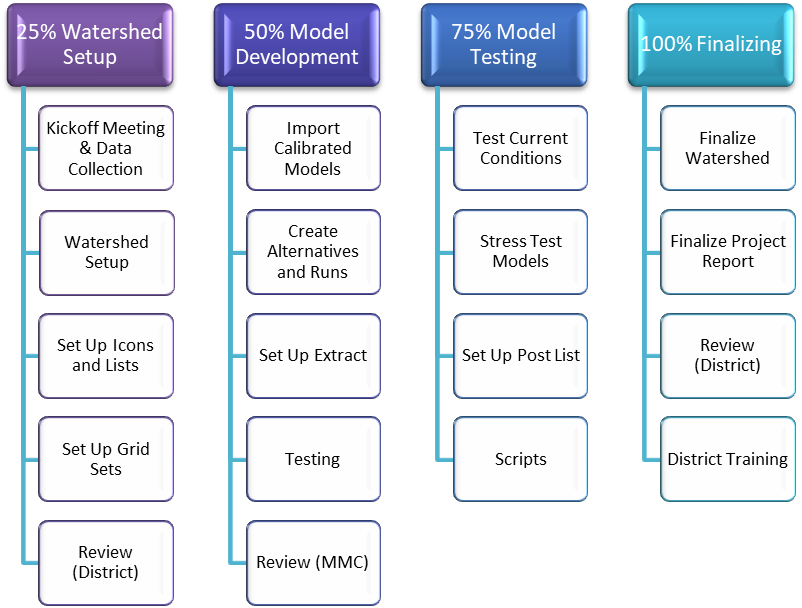
Figure 7-1. CAVI Watershed Workflow
7.2.1 Watershed Setup (25 Percent Milestone)
The watershed schematic identifies all the locations and areas within a watershed that are accessed by a user or have data exchange between models, including river reaches, sub-basin boundaries, time series locations, common computation points, levees, inundation areas, etc.
The deliverable for the 25 percent milestone is a CAVI watershed that has some basic data incorporated, including background maps, time series icons for observed data, gridded data, data status summary tables, and data validation lists.
7.2.2 Watershed Development (50 Percent Milestone)
The CWMS CAVI modeler is responsible for importing models into the CAVI and testing model connectivity. The modeler verifies location names are correct and consistent between models, and then links the models together to build a forecast run.
The deliverable for the 50 percent milestone is a CAVI watershed that incorporates the calibrated HEC-HMS, HEC-ResSim, HEC-RAS, and HEC-FIA models.
7.2.3 Watershed Testing (75 Percent Milestone)
Any changes made to the models between the 75 percent and 100 percent milestones will be incorporated into the CAVI watershed at this time. All scripts needed within the CAVI will also be implemented at this time.
The deliverable for the 75 percent milestone is a fully tested CAVI watershed that incorporates the final versions of the basin models.
7.2.4 Watershed Delivery (100 Percent Milestone)
Final cleanup and testing of the CAVI watershed are completed at this time. The district water management staff is also trained on use of the CAVI during this phase of the project.
The deliverables for the 100 percent milestone are the final CAVI watershed and the completed CAVI section of the project report.
7.3 Watershed Setup (25 Percent Milestone)
The initial setup of the CAVI watershed includes importing background maps, establishing time series icons, and ensuring data feeds are connected and functioning.
All modelers must agree on a common watershed schematic and naming convention early in the watershed setup process. Any changes made to the schematic (especially the stream alignment and common computation points) can cause significant re-work in one or more of the models. The team lead works with the CAVI modeler to ensure that all location names follow agreed upon conventions and are consistent for all models.
The deliverable for this milestone is a CAVI watershed that has completed data acquisition and visualization modules.
7.3.1 Watershed Setup
During this milestone the CAVI modeler begins to set up the CWMS watershed to visualize and validate available data in the CWMS database.
The following steps shall be performed during watershed setup:
- Create watershed and set map coordinates and time zone
- Import shapefiles
- Establish time series icons and data set properties
- Establish program order
- Set graphic properties
- Set up acquisition module
- Set up server configuration
7.3.1.1 Creating the Watershed
The first step is to create the watershed within the CAVI. The watershed name is uniquely identifiable within a national watershed library. Unless requested otherwise, use the three-digit district ID and primary river (e.g., MVS_Kaskaskia). Watershed descriptions are added to the model and include a statement that resembles the following example:
MVS Kaskaskia CWMS Watershed created for the MMC CWMS National Implementation Program [MMM YYYY]
The CAVI modeler also provides a brief description of the model and its purposes, including map coordinate information.
During the creation of the watershed, units shall be set based on the needs of the district. In most cases, English units are used. The time zone shall be Greenwich Mean Time (GMT) to allow seamless transfer of data between districts that reside in different time zones. District water managers can set the CAVI to display in their preferred time zone.
The map coordinates must be set to Albers Equal-Area Conic (SHG) with units as U.S. feet and spheroid as Geodetic Reference System 1980 (GRS 80) North Atlantic Datum of 1983 (NAD 83) when the watershed is created, as this is the MMC standard projection.
7.3.1.2 Importing Shapefiles
The CAVI modeler should import shapefiles to display in the map window. Shapefiles can be obtained from either the MMC GIS team member or the district staff. Common layers include stream centerlines, impact areas, gages, common computation points, and sub-basins. Gage locations may need to distinguish between stage/flow, elevation, and precipitation.
7.3.1.3 Establishing Time Series Icons and Data Set Properties
The CAVI modeler should create time series icons for all gages located within the study basin. Other time series icons are created to support the needs of the district office staff. For example, a time series icon can be created that shows inflow, pool elevation, and outflow for a reservoir in the system. The CAVI modeler coordinates this effort with district water managers.
At the same time, the CAVI modeler establishes data set properties for the time series icons with input from the district water managers. Refer to the CWMS User’s Manual for further instruction on how to create and edit time series icons.
7.3.1.4 Establishing Program Order
Unless otherwise defined in the HEMP as a specific requirement, the CAVI shall be set up to execute the program order shown in Figure 7-2.
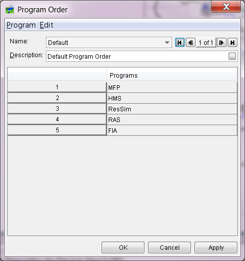
Figure 7-2. Sample Program Order
7.3.1.5 Graphic Properties
The graphic properties (colors, line weights, etc.) of map layers shall be adjusted to meet existing site conventions or specific preferences of the district.
7.3.1.6 Acquisition Module Setup
The CAVI modeler will complete the following steps in the acquisition module:
- Build critical data status reports
- Build data validation lists
- Set up quality color bar colors
7.3.1.7 Critical Data Status Reports
All necessary data should be added to a critical data status report list. Critical data is all observed or calculated data required for a CWMS model to run. This list tells the water manager which datasets are up to date in the database and helps verify the hour of the most current full dataset. Other summary lists are created by the CAVI modeler based on district requirements. These report files reside in the watershed’s shared directory. A sample of a data status summary table is shown in Figure 7-3.
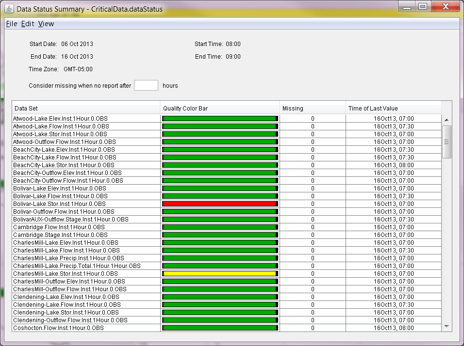
Figure 7-3. Example Data Status Summary Table
7.3.1.8 Data Validation Lists
Data validation lists are used by water managers to view and edit the data. Validation lists can be broken up in various ways. Examples of data groups are elevation, flow, and stage. Validation list files also reside in the watershed’s shared directory. A sample of a data validation list is shown in Figure 7-4.
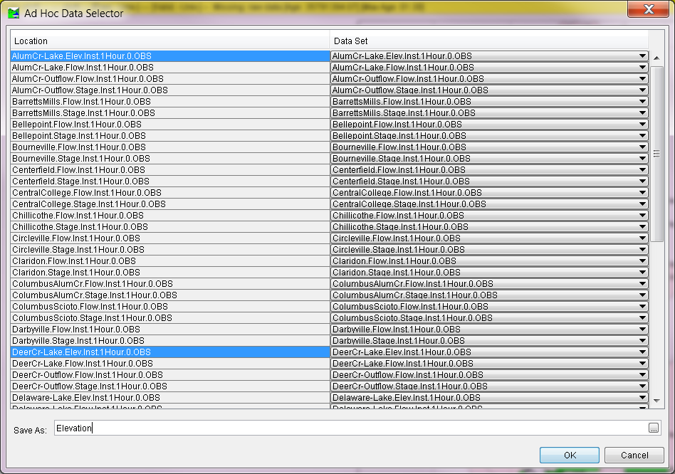
Figure 7-4. Example Data Validation List
7.3.1.9 Quality Color Bar Colors
The CAVI modeler sets up the quality color legend, as shown in Figure 7-5. Default colors are used unless the district requests otherwise.
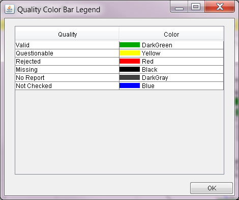
Figure 7-5. Quality Color Bar Legend
7.3.1.10 Server Configuration
If the team is accessing data from the CWMS server, the CAVI modeler will set up the login server ensuring the proper host address and port numbers are entered. The modeler will then switch the server from “local” to the CWMS server name and verify that the correct URLs are populated.
7.3.2 Visualization of Grid Sets
The CAVI modeler should set up grid sets from the Visualization tab within the CAVI. Grid sets should be set up for any meteorological data that will be used in a forecast (observed Stage III radar, QPF, temperature, snow water equivalent, etc.). This will allow the user to visualize the gridded data within the CAVI. The CAVI modeler should work with the System Administrator to ensure grids are clipped to the watershed area (with a small buffer). This will shorten the time needed to extract data from the CWMS database. The System Administrator should request assistance from their HEC Point of Contact if needed.
7.3.3 Creation of Dummy Watershed
The CAVI modeler should create a dummy watershed that will later be deleted. This watershed does not need to have any time series icons, grid sets, etc. It is only used to check naming and setup of the HEC-HMS and HEC-ResSim models. The CAVI modeler will import the 50 percent HEC-ResSim and HEC-HMS models. After the models are imported, the CAVI modeler will verify that there is only one junction at every junction location. If two junctions are very close to each other, the HEC-HMS and HEC-ResSim modelers need to edit the names of the junctions in each respective model to ensure they are identical. Once this process is complete, the modeler should delete the watershed.
7.3.4 Documentation of Watershed Setup
Once the initial CAVI watershed setup is complete, the modeler should obtain the CAVI section of the project report template and complete all relevant sections. Any assumptions or issues concerning the initial setup of the watershed should be documented at this time.
7.3.5 Interim Model Review (25 Percent Milestone Review)
Once the CWMS watershed has been created and the setup is complete, the modeler completes the 25 percent portion of the MMC CAVI review checklist. The modeler uploads a zipped copy of the preliminary watershed, the draft CAVI section of the project report, and the completed review checklist to the corresponding milestone folder on ProjectWise and submits the package for interim review.
7.3.6 Incorporating Review Comments
Any comments received from the 25 percent milestone review are addressed and incorporated into the watershed and draft CAVI section of the project report as needed.
7.4 Watershed Development (50 Percent Milestone)
Once the initial setup for the CAVI watershed is complete, the calibrated models will be integrated and tested. The models will be linked together, and the operations within the CAVI environment validated. Supplemental models will be integrated into the CAVI at this time, if required.
The deliverable for this milestone is a working CAVI watershed that includes all calibrated models (HEC-HMS, HEC-ResSim, HEC-RAS, and HEC-FIA).
7.4.1 Integrating Calibrated Models
The CAVI modeler will obtain copies of all models past the 75 percent model development milestone. This will allow the CAVI modeler to test connectivity between the individual models. If any discrepancies are found, the modelers need to correct the issues and resubmit them to the CAVI modeler for integration. This may be an iterative process.
7.4.1.1 Importing Standalone Models
The CAVI modeler imports the HEC-HMS, HEC-ResSim, HEC-RAS, and HEC-FIA models and model alternatives required within the CAVI. It is recommended to import the HEC-ResSim model first. HEC-HMS, HEC-RAS, and HEC-FIA models are then imported in that order. If the team is not developing a HEC-ResSim model for the basin, the CAVI modeler needs to build a stream alignment in the CAVI prior to importing any models.
NOTE
The CAVI modeler will ensure that the models imported are the cleaned-up versions (without large DSS files) of each of the models. This will prevent large, unnecessary files from being duplicated when forecasts are created.
If an existing Meteorological Forecast Processor (MFP) alternative or HEC-MetVue alternatives are not available, the CAVI modeler will be required to create a new meteorological alternative (with HEC-MetVue as the recommended utility) with the assistance from the HEC-HMS modeler.
7.4.1.2 Assigning Model Alternative Keys
The CAVI modeler will assign model alternative keys by choosing a letter or number for each model alternative. This task is coordinated with district water management staff.
7.4.1.3 Creating Forecast Runs
After all model alternative keys are created, the CAVI modeler will create a forecast run. A forecast run is a set of model alternatives that run sequentially during a forecast. The CAVI modeler will create as many forecast runs as needed, based on the operational needs of the district. Names of forecast runs are coordinated with district water management staff.
7.4.1.4 Model Linking
After a forecast run is created, the CAVI modeler will link the model alternatives. This is done using the model linking editor. This process ensures the output from one model is linked as input to another model. For example, modelers will want to use the output from MFP or HEC-MetVue as the input for HEC-HMS, and the output from HEC-HMS as the input for HEC-ResSim. The CAVI modeler needs to coordinate with each modeling team member to ensure the linking is correct. See the CWMS User Manual for further instructions on model linking.
7.4.2 Setting Up and Testing the Extract Process
The CAVI modeler sets up the extract groups once all models are imported into the CAVI. Extract groups are created for all data needed to run and calibrate the models within the CAVI. Once the extract groups are created, the modeler assigns DSS pathnames to the observed data within the CWMS database. Coordination between the MMC team and district is recommended during this process. An example of the extract editor window is shown in Figure 7-6.
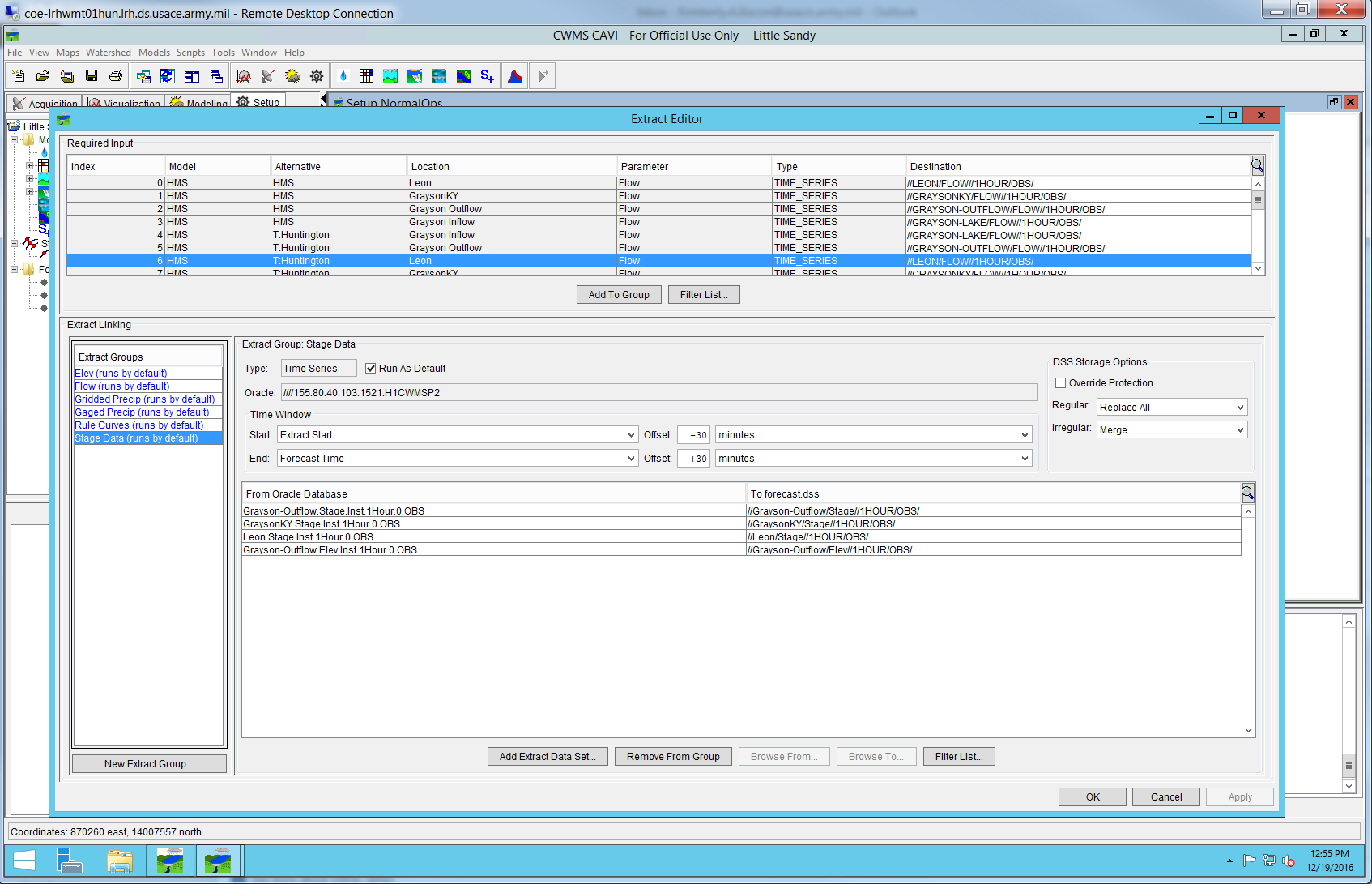
Figure 7-6. Example Extract Editor
The CAVI modeler tests the extract process to ensure it is functioning properly by creating a new forecast run. This forces the CAVI to extract data using the extract groups. Using CWMS-Vue, the modeler can view the forecast.dss file to verify all data is extracted from the Oracle database correctly. Any errors occurring during the extract process are displayed in the extract tab.
It is important to note the modeler may need to extract data beyond the start time of the forecast to ensure the datasets are complete and the models will run. If the district has data that comes in on the half hour (ex: 0730) the modeler adds a 30-minute offset to the extract group. If the groups are set up to have a -30 minute prior to extract and a +30 minute past forecast time, the extract will get data 30 minutes before the extract time and 30 minutes past the forecast time. This ensures a complete dataset is extracted and available for the forecast.
7.4.3 Validating Operations
The CAVI modeler executes a test forecast of the watershed to ensure the models are linked together correctly. It is necessary for the CAVI to extract real-time data, build a forecast.dss file, run a forecast without major errors, and produce reasonable results.
7.4.4 Documentation of Watershed Development
Once the initial CAVI watershed development is complete, the modeler should obtain the draft CAVI section of the project report completed for the 25 percent milestone review and update the report as necessary. Any assumptions or issues concerning the development of the CAVI watershed should be documented at this time.
7.4.5 Interim Model Review (50 Percent Milestone Review)
Once the models have been imported into the CAVI watershed and tested, the modeler completes the 50 percent portion of the MMC CAVI review checklist. The modeler uploads a zipped copy of the preliminary watershed, the draft CAVI section of the project report, and the completed review checklist to the corresponding milestone folder on ProjectWise and submits the package for interim review.
7.4.6 Incorporating Review Comments
Any comments received from the 50 percent milestone review are addressed and incorporated into the watershed and draft CAVI section of the project report as needed.
7.5 Watershed Testing (75 Percent Milestone)
During this phase, the final models will be incorporated into the CAVI if any changes were made between the 75 percent and 100 percent milestones. The CAVI will also be stress tested by running hypothetically large events to ensure the models are robust and can withstand a wide range of events. Any scripts and reports required will be incorporated at this time.
The deliverable for this milestone is a CAVI watershed model that has the 100 percent models incorporated and tested.
7.5.1 Final Model Integration
The CAVI modeler will import the final versions of the models into the CAVI if there were any significant changes between the 75 percent and 100 percent milestones. The modeler should follow the procedures listed in Section 7.4.1 to accomplish this task.
7.5.2 Testing the Models Using Real-Time Events
The CAVI modeler tests the models using current data and conditions within the watershed and ensures the results are close to the observed. The CAVI modeler works closely with each modeling team member to review the results from each forecast run.
7.5.3 Testing the Models Using Hypothetically Large Events
The CAVI modeler should stress test the models with a large simulated rainfall event. This shows potential weaknesses that could prevent the models from running during a real flood event. For example, a rating table may not extend high enough to include large flows. If any problems are identified by the CAVI modeler, the modelers are notified and changes are made so the forecast can run successfully.
7.5.4 Adding and Testing Scripts and Reports
The CAVI modeler will import and test the datum conversion script if needed. This script is set up to convert the forecast.dss file elevation data from National Geodetic Vertical Datum of 1929 (NGVD 29) to NAVD 88 vertical datum. If the district is already storing data in the NAVD 88 vertical datum, this script is not necessary. Other scripts that may be specific to the watershed should be incorporated and tested at this time.
Any reports requested by the district and documented within the HEMP should be developed by the CAVI modeler at this time.
7.5.5 Setting Up the Post Group
The CAVI modeler sets up the post groups in the CAVI. Post groups should be created for any forecast data that the district wants to store in the CWMS database. Once the post groups are created, the modeler assigns Oracle database paths to the forecasted data coming from the model results. Coordination between the CAVI modeler and district is recommended during this process.
7.6 Watershed Delivery (100 Percent Complete)
The final steps in the CAVI watershed development process include final testing and setup of the watershed for use in real-time forecasting. If requested by the district, the team forecasting option will be set up during this phase. The workflow tab within the CAVI may also be developed during this phase.
The deliverables for this milestone are a fully functioning CAVI watershed and the completed CAVI section of the project report.
7.6.1 Model Testing
The CAVI modeler, with assistance from the team, ensures all final models are working properly within the CWMS CAVI environment. This confirms the models are ready for final delivery and district training. The CAVI modeler, with the assistance of the other modelers on the PDT, will review model results computed in the CAVI and quickly verify model calibration.
7.6.2 Team Forecasting
The CAVI modeler will set up the team forecasting option within the watershed if requested by the district water management staff. Refer to the CWMS User’s Manual on how to set up team forecasting.
7.6.3 Workflow Tab
If requested by the district water management staff, the CAVI modeler should set up the workflow tab and add any common tasks, such as scripts or model computes. Refer to the CWMS User’s Manual for more information.
7.6.4 Documentation of Final Watershed Development
The section of the project report covering the CAVI Watershed development should be almost complete at this point, as it builds on the draft report written for the previous project milestones. Any additional information or items of interest not previously discussed are added to the report as needed. Documentation of any unresolved issues that may impact real-time operations or model results is important.
7.6.5 Final Review (100 Percent Milestone Review)
Once the CAVI watershed has been finalized, the modeler completes the 100 percent portion of the MMC CAVI review checklist. The modeler uploads a zipped copy of the final watershed, the final CAVI section of the project report, and the completed review checklist to the corresponding milestone folder on ProjectWise and submits the package for final review.
7.6.6 Incorporating Review Comments
Any comments received from the 100 percent milestone review are addressed and incorporated into the watershed and final CAVI section of the project report as needed.
7.6.7 Final Watershed Storage
The CAVI modeler uploads all project data, documentation, and a zipped copy of the final CAVI watershed to the corresponding folder on ProjectWise. The CAVI modeler or CWMS team lead ensures all models and files are delivered to the district and, if needed, uploaded to the water management server. For more information, see Section 10.
7.7 Reference material
The following sources may be helpful to team members developing the CAVI. Team members can locate these sources by following the citation information found in Section 12.
- CWMS User’s Manual
- PROSPECT Course Materials
- CWMS Modeling for Real-Time Water Management
Section 8 - Corps Water Management System Administration
This section describes the responsibilities of the system administrator during the entire project, starting with data collection and ending with final testing of the CAVI watershed.
8.1 Overview
The district CWMS system administrator is responsible for ensuring the availability of hydrometeorological data, real-time and historic, within CWMS. The district CWMS system administrator provides CWMS server account access and supports data acquisition. Most of the activities occur prior to or shortly after the kickoff meeting. However, the district CWMS system administrator may be needed during later milestones if additional hydromet data is required. In summary, the district CWMS system administrator is responsible for supporting the data and IT requirements of the CWMS modeling team.
8.2 Administrator Setup
The CWMS system administrator begins focusing efforts on any data acquisition needs identified during kickoff the meeting. They grant each essential MMC CWMS team member CWMS server access and set permissions as needed to perform model development. The CWMS system administrator should coordinate with the team lead to ensure that the modelers are using the version of CWMS that matches the server version.
8.2.1 Account Access
Once the MMC CWMS team roster is finalized, the CWMS system administrator provides access for any team member that needs to log into the server.
8.2.2 Software Versions
The CWMS system administrator and the CWMS team lead will be responsible for ensuring the CWMS modeling team members are using the correct version of the CWMS CAVI and accompanying software packages that align with the version on the district server.
8.2.3 Kickoff Meeting
The CWMS system administrator is responsible for participating in the kickoff meeting to provide support and knowledge regarding the CWMS server, to discuss account access issues, and to determine the data needs of the team for real-time and historic data. These findings and decisions are documented in the HEMP.
8.3 Administrator Support
The CWMS system administrator ensures real-time data feeds are working in the CWMS database for the team to use in model development. They also work to gather and disseminate the historic data needed for model calibration.
8.3.1 Real-Time Data
The CWMS system administrator ensures all required data streams are functioning in the CWMS database. If any required data stream is not currently available in the CWMS database, the administrator develops the required processes to begin acquisition of the data.
The CWMS system administrator ensures the following data streams are operating to provide real-time data within CWMS:
- Geostationary Operational Environmental Satellite System (GOES) data collection platform (DCP) gage data
- NOAA radar and QPF spatial products
- National Weather Service river forecasts
- Other data streams as specified in the HEMP
The CWMS system administrator is required to provide the necessary data prior to the end of the 25 percent model development milestones for HEC-HMS, HEC-ResSim, and HEC-RAS. The CWMS system administrator is also responsible for ensuring processes are in place for the necessary data conversions (stage-flow, point-spatial, source datum-88datum, etc.).
8.3.2 Historic Data
The CWMS system administrator provides historic hydrometeorological data for model calibration. All historic data is delivered prior to the end of the 25 percent model development milestones for HEC-HMS, HEC-ResSim, and HEC-RAS.
8.4 Final Deliverables
The CWMS system administrator provides data necessary to produce the CWMS project report to the CWMS team lead or CAVI modeler, including sources of data acquisition, assumptions, and difficulties. The CWMS system administrator is also responsible for providing any necessary data to the CWMS team lead in preparation for the product delivery meeting and ensuring all data feeds in the CWMS servers are working so a real-time forecast can be demonstrated during the product delivery meeting.
8.5 Reference Material
- CWMS Administration Manual
- CWMS User’s Manual
Section 9 - Developing the Project Report
This section describes the process of developing and reviewing the project report.
9.1 Preparing the project report
The CWMS team lead ensures project report development occurs within the latest report template. The team lead will load a copy of the template into the Reports folder under each model discipline folder (e.g. HMS, RAS, and ResSim) for the modelers to update their assigned section(s) of the report. Figure 9-1 shows the folder structure used in ProjectWise to store all of the draft versions and final copies of the project report.
9.2 Developing the project report
Each CWMS modeler will only update their assigned sections of the report. The modeler will not edit or reformat the report, but will only add content to the document. When the modeler has successfully completed their section, the modeler will load the completed report to the respective project folder. See Appendix 3.1.8 for further guidance on CWMS report creation.
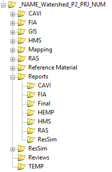
Figure 9-1. CWMS Project Report Folder Structure
The CWMS team lead will review the draft content for all sections within the project report and will work with the assigned modeler(s) if edits need to be made. Ultimately, the CWMS team lead is responsible for the technical content that comprises the CWMS project report.
The following are reminders for the CWMS modeler to consider when developing his or her section of the report:
- Use present tense
- Use the National Centers Supporting Dam and Levee Safety Style Guide as a reference; the CWMS report template format aligns with the style guide requirements
- Style Guide: Click here for the style guide.
- Overwrite the sample green text
- Change green text to black after edits are complete
- Delete template Comments associated with reminders
- Team lead (TL) responds to technical editor (TE) comments during technical edit review, please do not delete them
- Do not use screenshots or figures for tables (a table is something that can be manipulated)
- Do not use charts for figures (the plot lines etc. on charts get skewed during editing/formatting)
- Do not put figures or tables side by side on a page, insert the item leaving two lines between them
- Ensure all tables and figures are referenced (by number) in the text before they appear in the document
- Do not use landscape tables, figures, pages except in appendices
- CWMS report cover photo should be provided by the district, not a a screenshot from Google Earth or any other satellite image
- If acronyms or abbreviations are not in the list at the back of the report, please write them out the first time and flag them with a comment so the documentation team can tehm to the list
When the CWMS team lead has confirmed all sections of the report are developed and reviewed, the team lead contacts the CWMS technical editor or the MMC documentation lead to schedule the technical review of the project report. The documentation lead requests the CMWS team lead notify the documentation team by email one month prior to the estimated start date of the technical review.
9.3 Technical and Management Review Process
The MMC documentation lead and assigned CWMS technical editor are the points of contact for the technical review of the CWMS project report.
The technical review process includes, but is not limited to, combining each model section into a master draft report; updating table and figure numbering sequences; validating pertinent dam information by comparing WCM and project report values; sentence structure; spell check; document formatting; confirming points of contact; and other functions as required.
Technical review steps for success:
- CWMS team lead has each assigned modeler complete their section in the draft project report and confirm status prior to sending the document to the CWMS team lead for initial review.
- CWMS team lead will schedule a collaboration meeting at the 75 percent milestone complete status with the technical editor.
- CWMS team lead emails the technical editor with estimated date when the report will be handed off to the technical editor (one month in advance). The technical editor will pencil in the technical review in the team schedule.
- Technical editor sews together the draft report and conducts the technical review (the documentation lead can help with assembling the report sections, if requested).
- CWMS team lead works with technical editor to clear outstanding comments and approve edits.
- Technical editor contacts the documentation lead when the report is ready for management review.
- The documentation lead finalizes the management review and contacts the technical editor and CWMS team lead with status.
- The report is finalized and printed to a PDF. Final report will be loaded to the project folder under the Reports/Final folder on ProjectWise.
- All track change files are archived by the technical editor in the Reports/Final/Archive folder.
- The report is signed by the MMC Director.
The report is a living document and can be updated if needed. The CWMS technical lead is responsible for archiving a copy of the final report prior to updating the document.
Section 10 - Corps Water Management System Watershed Delivery and Training
The intent of the CWMS watershed delivery and training is for the CWMS team lead and CAVI modeler to provide the deliverables and train the staff on how to use the models. This meeting should occur after the CWMS models have been calibrated, integrated, and tested on the CWMS water management server.10.1 Coordination Meeting
The CWMS team lead coordinates the handoff meeting with the district water management office to ensure key personnel are available and a conference room with necessary equipment is reserved (if an in-person meeting is required).
10.2 Product Delivery Meeting Presentation
The product delivery meeting presentation is prepared by the CWMS team lead to be presented during the meeting. It is encouraged that the following branch/section chiefs receive an invitation to the presentation portion of the meeting: Engineering and Construction, Hydrology and Hydraulics, Water Management, and others determined essential by the district. The presentation should, at a minimum, review the following content: project overview, HEMP requirements, CWMS model development summary, and the project report.
10.2.1 Project Overview
The CWMS team lead will give a brief overview of the project and the goals for the handoff meeting. Other items to discuss include the MMC SharePoint site, ProjectWise file storage, the Microsoft Teams group for CWMS modelers, and how to access MMC guidance documents.
10.2.2 Hydrologic Engineering Management Plan
The CWMS team lead reviews the HEMP during the meeting to ensure the path agreed upon during the kickoff meeting was followed.
10.2.3 Model Development Summary
The CWMS team lead, with assistance from other PDT members, will discuss the development of each model to the district personnel. The team lead or modeler should provide a brief overview of the model including key assumptions, modeling difficulties, calibration results, model limitations, and suggestions for future improvements.
10.2.4 Project Report
The CWMS team lead briefly reviews the project report and provides a copy to the district during the meeting.
10.3 Control and Visualization Interface Demonstration
The CAVI modeler or team lead will demonstrate how to use the CAVI watershed by running through an example forecast for the basin. The CAVI modeler should demonstrate how to accomplish the following tasks:
- Demonstrate how to calibrate the HEC-HMS and HEC-RAS model parameters
- Access and change HEC-ResSim rules
- Override HEC-ResSim releases within the OSI
- Review model results
- Generate inundation products using RAS Mapper
- Utilize any custom scripts
- Generate any custom reports.
10.4 Model Limitations and Future Improvements
The CWMS team lead discusses model limitations with the district water management staff. The CWMS team lead should also provide a list of improvements the district can address during implementation of the models.
10.5 Final Deliverables
During the product delivery meeting, the CWMS team lead presents the final deliverables to the district, including the HEMP, project report, and final models.
Section 11 - External Deliverables
This section summarizes the products available at the end of an MMC CWMS watershed study, the review steps undertaken during the production process, and USACE policy and guidance for product handling and dissemination.
11.1 Modeling, Mapping, and Consequences Products
MMC production center deliverables produced using this technical manual and the servers where they are located are:
- Flood Inundation Mapping (FIM) Data Viewer https://fim.sec.usace.army.mil/viewer/
- Final modeling data layers
- MMC ProjectWise CWMS Folder pw://PWINT-WPC.EIS.DS.USACE.ARMY.MIL:CE&space;-&space;MMC/Documents/Programs&space;and&space;Activities/MMC2/Corps&space;Water&space;Management&space;System&space;(CWMS)/
- HEMP
- Final Report
- Final Models
11.1.1 Reference Material
The reference material deliverable contains all materials used in model development. All data supporting the models should be included. This data may be, but is not limited to, the following:
- Existing models
- Hydrology data
- Period of record (POR) data
- Volume duration frequency (VDF) analysis data
- WCM(s)
- Previous basin study reports
- LiDAR or other ground surface data
- Channel bathymetry
- Bridge/Structure data
- Dam Safety Reports (semi quantitative risk assessment [SQRA], IES, etc.)
- Other pertinent information.
11.1.2 Final Watershed and Models
A copy of the final watershed and all of the models developed during the MMC CWMS implementation will be delivered to the district during the product delivery meeting. These models should also be loaded onto the district’s CWMS server for use in real-time forecasting.
11.1.3 Hydrologic Engineering Management Plan
A copy of the signed HEMP should be provided to the district at the end of the project, as this document helped guide the team during the development of the CWMS watershed. Refer to Section 1.6.1 for more information about the development of the HEMP.
11.1.4 Project Report
A project report is developed for each MMC CWMS watershed project. The report is intended to summarize the basin characteristics, assumptions, and difficulties of model development, as well as HEC-HMS, HEC-ResSim, HEC-RAS, and HEC-FIA model results. See Section 9 for further details.
11.1.5 Summary of All Reviews
This deliverable contains all review comments and correspondence pertaining to the reviews. The MMC CWMS review checklist is utilized for all model reviews (see Appendix 3.3).
11.1.6 Mapping Products
Mapping file geodatabase, output files, Keyhole Markup (KMZ) files for Google Earth, and PDF map products that were developed during the project are delivered to the district.
11.2 Review Process Summary
This section lists the review steps performed during the development of the MMC CWMS models. Internal MMC reviews and external reviews are described in detail in Sections 11.2.1 and 11.2.2.
11.2.1 Internal Reviews
The internal reviews of the CWMS products are conducted by the following personnel:
- Pre-model GIS data review—CWMS mapping technical lead
- HEMP review—CWMS technical lead
- 50 percent model review—independent review team (typically HEC and MMC staff)
- HEC-FIA model review—CWMS consequences technical lead
- Mapping internal review—CWMS mapping technical lead
- Project Report final internal technical review—documentation lead.
11.2.2 External reviews
The external reviews of the CWMS products will be conducted by the following personnel:
- 25 percent model review—District POC
- 75 percent model review—District POC
- 100 percent model review—District POC.
11.3 Data Handling
Data distributed from the MMC is considered controlled unclassified information. It contains information that may require safeguarding or dissemination controls pursuant to and consistent with applicable law, regulations, and government-wide policies, but is not classified information. It is to be controlled, stored, handled, transmitted, distributed, and disposed of in accordance with DOD Instruction 5200.48, Controlled Unclassified Information.
The MMC is responsible for development of the products while the districts are responsible for maintaining and managing the models after delivery. Districts are responsible for data dissemination to external stakeholders. The MMC will not disseminate products to external stakeholders except in special circumstances with either the concurrence of or at the request of a water manager (district, division, or USACE).
MMC products are finalized via resolution of comments received in the reviews discussed previously. Draft and final products are available to the district for download via ProjectWise. Upon receipt of the products, further dissemination of the data to other stakeholders becomes the responsibility of the water management staff (district, division, or USACE). The district is primarily responsible for determining the proper use and distribution of the data, including dissemination to local governments or emergency response agencies in accordance with current USACE policy on release of information.
Appendix 6 provides copies of the following guidelines and policies for dissemination of MMC products:
- USACE RMC, 18 May 2010, “Safeguarding Sensitive Information–Modeling, Mapping and Consequences Production Center.” Overview of MMC policy discussing the rest of the documents in this list.
- Draft usage agreement for submittals to external stakeholders.
Section 12 - Sources of Information
This section provides information on data and documentation that may be relevant to the development and implementation of CWMS models.
12.1 data sources, Guidance, and Procedures
Environmental Systems Research Institute, Inc. (ESRI). 2021. “ArcGIS Living Atlas of the World” Accessed July 15. https://livingatlas.arcgis.com/en/home/.
Federal Emergency Management Agency (FEMA).2013. Publication 64, “Federal Guidelines for Dam Safety, Emergency Action Planning for Dam Owners,” Washington, D.C.: Federal Emergency Management Agency (FEMA) U.S. Department of Homeland Security (DHS).
———. 2021. “Hazards U.S. (HAZUS) Data”. Accessed July 15. https://www.fema.gov/flood-maps/products-tools/hazus.
Gesch, D., Oimoen, M., Greenlee, S., Nelson, C., Steuck, M., and Tyler, D. 2002. “The National Elevation Dataset: Photogrammetric Engineering and Remote Sensing,” v. 68, no. 1, 5-11.
National Climactic Data Center (NCDC). 2021. “Climate Data Online Search.” Accessed July 15. https://www.ncdc.noaa.gov/cdo-web/search.
National Oceanic and Atmospheric Administration. 2021. National Centers for Environmental Information. “Radar Data.” Accessed July 15. https://www.ncdc.noaa.gov/data-access/radar-data.
United States Census Bureau. 2021. “Census Data.” Accessed July 15. http://www.census.gov/data.html.
U.S. Department of Agriculture. 2021. Farm Service Agency. “National Agriculture Imagery Program (NAIP) Imagery.” Accessed July 15. https://www.fsa.usda.gov/programs-and-services/aerial-photography/imagery-programs/naip-imagery/.
———. 2021. Natural Resources Conservation Service. “Soil Geography.” Accessed July 15. https://www.nrcs.usda.gov/wps/portal/nrcs/main/soils/survey/geo/.
U.S. Geological Survey. 2021. “Land Use Land Cover Modeling.” Accessed July 15. https://www.usgs.gov/core-science-systems/eros/lulc.
———. 2021. “National Hydrography.” Accessed July 15. https://www.usgs.gov/core-science-systems/ngp/national-hydrography.
———. 2021. “The National Map.” Accessed July 15. https://www.usgs.gov/core-science-systems/national-geospatial-program/national-map.
———. 2021. “Water Data for the Nation.” Accessed July 15. https://waterdata.usgs.gov/nwis.
———. 2021. “Watershed Boundary Dataset.” Accessed July 15. https://www.nrcs.usda.gov/wps/portal/nrcs/main/national/water/watersheds/dataset/.
U.S. Army Corps of Engineers. 1985. Engineer Manual 1110-2-1701: Hydropower. Washington, D.C.: U.S. Army Corps of Engineers.
———. 1991. Engineer Regulation 1110-8-2(FR): Inflow Design Floods for Dams and Reservoirs. Washington, D.C.: U.S. Army Corps of Engineers.
———. 1993. Engineer Manual 1110-2-1416: River Hydraulics. Washington, D.C.: U.S. Army Corps of Engineers.
———. 1994. Engineer Manual 1110-2-1417: Flood Runoff Analysis. Washington, D.C.: U.S. Army Corps of Engineers.
———. 2003. Economic Guidance Memorandum 04-01: Generic Depth-Damage Relationships for Residential Structures with Basements. Washington, D.C.: U.S. Army Corps of Engineers.
———. 2017. Engineer Manual 1110-2-3600: Management of Water Control Systems. Washington, D.C.: U.S. Army Corps of Engineers.
———. 2018. Engineer Manual 1110-2-1420: Hydrologic Engineering Requirements for Reservoirs. Washington, D.C.: U.S. Army Corps of Engineers.
———. 2020. Engineering Circular 1110-2-6075: Inundation Maps and Emergency Action Plans and Incident Management for Dams and Levee Systems. Washington, D.C.: U.S. Army Corps of Engineers.
U.S. Army Corps of Engineers, Hydrologic Engineering Center (HEC). 1980. Guideline RD-13, “Flood Emergency Plans—Guidelines for Corps Dams,” USACE Hydrologic Engineering Center, Davis, CA, June.
———. 2021. “HEC-HMS User’s Manual,” Davis, CA, Accessed July 28. https://www.hec.usace.army.mil/confluence/hmsdocs/hmsum/latest.
———. 2021. “HEC-HMS Technical Reference Manual,” Davis, CA. https://www.hec.usace.army.mil/confluence/hmsdocs/hmstrm.
———. 2021. “HEC-HMS Applications Guide,” Davis, CA. https://www.hec.usace.army.mil/confluence/hmsdocs/hmsag.
———. 2021. “HEC-HMS Tutorials and Guides,” Davis, CA. https://www.hec.usace.army.mil/confluence/hmsdocs/hmsguides.
———. 2021. “HEC-ResSim User’s Manual,” Davis, CA. https://www.hec.usace.army.mil/software/hec-ressim/documentation/HEC-ResSim_33_UsersManual.pdf.
———. 2021. “HEC-ResSim Quick Start Guide,” Davis, CA. https://www.hec.usace.army.mil/software/hec-ressim/documentation/HEC-ResSim_33_QuickStartGuide.pdf.
———. 2021. “HEC-RAS User’s Manual,” Davis, CA. https://www.hec.usace.army.mil/confluence/rasdocs/rasum/latest.
———. 2021. “HEC-RAS 2D User’s Manual,” Davis, CA. https://www.hec.usace.army.mil/confluence/rasdocs/r2dum/latest.
———. 2021. “HEC-RAS Mapper User’s Manual,” Davis, CA. https://www.hec.usace.army.mil/confluence/rasdocs/rmum/latest.
———. 2021. “HEC-RAS Hydraulic Reference Manual,” Davis, CA. https://www.hec.usace.army.mil/confluence/rasdocs/ras1dtechref.
———. 2021. “HEC-FIA User’s Manual,” Davis, CA. https://www.hec.usace.army.mil/confluence/fiadocs/fiaum/latest.
———. 2021. “CWMS User’s Manual,” Davis, CA. https://www.hec.usace.army.mil/confluence/cwmsdocs/cwmsum/latest.
———. 2021. “HEC-DSSVue User’s Manual,” Davis, CA. https://www.hec.usace.army.mil/confluence/dssvuedocs/latest.
Glossary
Two-Dimensional Model. The MMC Production Center standard for two-dimensional (2D) modeling is HEC-RAS 6.0. HEC-RAS 6.0 is a finite difference hydraulic model that can simulate channel flow and unconfined overland flow.
Active Storage Water Elevation (feet). Maximum reservoir water surface obtained when the reservoir is fully utilized for all purposes, including conservation and flood storage. This elevation represents the highest elevation obtained under normal regulated operating conditions. This water surface elevation corresponds to the top of active storage level.
Alternative:
Forecast Alternative. Set of CAVI model alternatives that run sequentially during a forecast (also referred to as Forecast Run).
Model Alternative. Consists of input data sets for each model, and they exist independent of time.
Banklines (Pertaining to HEC- River Analysis System [HEC-RAS]). A Geographic Information System (GIS) shapefile that represents where banks are located along a particular river reach.
Bathymetric Data. The measurement of the depths of oceans, seas, or other large bodies of water.
Blocked Obstructions (Pertaining to HEC-RAS). Areas within cross sectional flow areas that are blocked from containing water in a particular cross section.
Centerline (River Centerline). Water surface course centerlines for a waterway defined by digitizing centerlines atop a contiguous imagery source.
Conversion Points. Nationwide point features containing interpolated values at point locations. Conversion points contain the elevation difference between National Geodetic Vertical Datum of 1929 (NGVD 29) and North American Vertical Datum of 1988 (NAVD 88). This point shapefile can be used to update raster value fields. See the National Geodetic Survey website for additional information: https://www.ngs.noaa.gov/.
Consequences. Potential loss of life or property damage caused by floodwaters released at the dam or by uncontrolled runoff.
Critical Infrastructure. Defined in the U.S. Patriot Act as those systems and assets, whether physical or virtual, so vital to the United States that the incapacity or destruction of such systems and assets would have a debilitating impact on security, national economic security, national public health or safety, or any combination of those matters.
Dam Safety Action Classification (DSAC). A dam classification system created by U.S. Army Corps of Engineers dam safety professionals to group dams that exhibit certain characteristics for potential safety concerns.
Data Acquisition. The act of acquiring data from other sources.
Depth Grid. Depth raster datasets that represent the depth of flooding encountered throughout the inundation area.
Design Memorandum (DM). Notes or plans corresponding to a design.
Drainage Area (square miles). Surface area that drains to a particular point (in this case, the dam) on a river or stream. Same as data field 33 in the National Inventory of Dams, Version 4.0, April 2008.
Emergency Action Plan (EAP). A plan of action to be taken to reduce the potential for property damage and loss of life in an area affected by a dam failure or large flood.
External Deliverables. Deliverables produced during and from the MMC Production Center's production cycle that are to be considered final end products for the intended customer.
Flow Path. The centroid of a particular flow area within a model cross section.
Forecast. Application of science, technology, and models to predict future weather and stream stages.
Geodatabase. An ArcGIS geodatabase is a collection of geographic datasets of various types held in a common file system folder, a Microsoft Access database, or a multiuser relational database (such as Oracle, Microsoft SQL Server, or IBM DB2).
Hydrograph Routing. The act of accounting for inflow and outflow rates, water storage characteristics, and losses for a particular river reach or reservoir.
Ineffective Flow Areas (Pertaining to HEC-RAS). Areas within a cross section representing flood plain flow that do not convey water downstream.
Inline Structures (Pertaining to HEC-RAS). A physical feature that generally lies perpendicular to flow and impounds water (such as a dam). Water may be routed through or over this structure.
Internal Deliverables. Deliverables created during the MMC Production Center production cycle and disseminated between team leads and/or team members.
Lateral Structures (Pertaining to HEC-RAS). A physical feature that generally lies parallel to flow. Water may be routed over this structure.
Kickoff Meeting. Meeting held at the district prior to model development to orient the CWMS MMC team members with the watershed and provide close coordination with the district
Manning's "n" Values. A scale of relative roughness pertaining to stream channels and overbank areas.
Probable Maximum Flood (PMF). The most likely largest inflow event (volume-based) produced by the probable maximum precipitation (PMP) that will occur over a watershed.
Rating Curves. A relationship between the flow and corresponding elevation at specific location on the river or stream.
Model Geometry (Pertaining to HEC-RAS). A representation of the physical features that impact flow in a particular modeled reach.
Storage. The retention of water or delay of runoff either by planned operation, as in a reservoir, or by temporary filling of overflow areas, as in the progression of a flood wave through a natural stream channel. Definitions of the specific types of reservoir storage are as follows:
Active Storage. The volume of the reservoir that is available for some use such as power generation, irrigation, flood control, water supply, etc. The bottom elevation is the minimum operating level.
Dead Storage. The storage that lies below the invert of the lowest outlet. This type of storage cannot readily be withdrawn from the reservoir.
Flood Surcharge. The storage volume between the top of the active storage and the design water level.
Inactive Storage. The storage volume of a reservoir between the crest of the invert of the lowest outlet and the minimum operating level.
Live Storage. The sum of the active and inactive storage.
Reservoir Capacity. The sum of the dead and live storage of the reservoir.
Storage Area Connections (Pertaining to HEC-RAS). A physical feature that lies between two HEC-RAS storage areas over which water may be routed.
Storage Curves (Pertaining to Reservoir Storage). A relationship between reservoir pool elevation and corresponding storage volume.
Study Area. An estimated inundation area created by GIS from buffering the centerline to create the 10-meter digital elevation model (DEM) for pre-model GIS process.
Unsteady Flow Modeling. Hydraulic modeling that involves routing a hydrograph though a system.
USACE Dam Safety Program. The USACE Dam Safety Program effectively attempts to apply the utmost care and competence to every aspect of dam design, construction, operation, and maintenance.
Water Control Manual. Document containing information pertaining the corresponding dam and reservoir. This information may include, but is not limited to, construction plans, operational procedures, and exceedance duration curves.
Watershed. An extent or an area of land where surface water from rain and melting snow or ice converges to a single point at a lower elevation.
| 1D | one-dimensional |
| 2D | two-dimensional |
| AG | advisory group |
| CAVI | Control and Visualization Interface |
| CCP | common computation point |
| cfs | cubic feet per second |
| CWMS | Corps Water Management System |
| DCP | data collection platform |
| DEM | Digital Elevation Model |
| DHS | Department of Homeland Security |
| DM | Design Memorandum |
| DSAC | Dam Safety Action Classification |
| EAP | Emergency Action Plan |
| EM | Engineer Manual |
| EoS | end of simulation |
| ER | Engineer Regulation |
| ESRI | Environmental Systems Research Institute |
| FDR | flood damage reduction |
| FEMA | Federal Emergency Management Agency |
| FIM | Flood Inundation Mapping |
| FIS | Flood Insurance Study |
| FY | fiscal year |
| GIS | Geographic Information Systems |
| GMT | Greenwich Mean Time |
| GOES | Geostationary Operational Environmental Satellite System |
| GRS 80 | Geodetic Reference System 1980 |
| gSSURGO | gridded Soil Survey Geographic Database |
| HAZUS-MH | Hazards U.S. Multi-Hazard (Database from FEMA) |
| HEC | Hydrologic Engineering Center |
| HEC-DSS | Data Storage System |
| HEC-FIA | Flood Impact Analysis |
| HEC-HMS | Hydrologic Modeling System |
| HEC-RAS | River Analysis System |
| HEC-ResSim | Reservoir System Simulation |
| HEMP | Hydrologic Engineering Management Plan |
| H&H | Hydraulics and Hydrology |
| HQ | headquarters |
| HRAP | Hydrologic Rainfall Analysis Projection |
| HUC | hydrologic unit code |
| IES | Issue Evaluation Study |
| IOP | Interim Operating Plan |
| IRRM | Interim Risk Reduction Measures |
| IT | Information Technology |
| KMZ | Keyhole Markup (file), Zipped |
| LiDAR | Light Detection and Ranging |
| LULC | Land Use Land Cover |
| MFP | Meteorological Forecast Processor |
| MMC | Modeling, Mapping, and Consequences |
| MPE | multisensory precipitation estimator |
| MVS | U.S. Army Corps of Engineers, St. Louis District |
| NAD 83 | North Atlantic Datum of 1983 |
| NASS | National Agricultural Statistics Service |
| NAVD 88 | North American Vertical Datum of 1988 |
| NED | National Elevation Dataset |
| NEXRAD | next-generation radar |
| NGVD 29 | National Geodetic Vertical Datum of 1929 |
| NHD | National Hydrography Dataset |
| NLCD | National Land Cover Dataset |
| NLD | National Levee Database |
| NOAA | National Oceanic and Atmospheric Administration |
| NSI | National Structure Inventory |
| NWS | National Weather Service |
| OSI | Operations Support Interface |
| PA | periodic assessment |
| Portable Document Format | |
| PDT | Project Delivery Team |
| PMF | probable maximum flood |
| POC | point of contact |
| POR | period of record |
| QC | quality control |
| QPF | Quantitative Precipitation Forecast |
| RMC | Risk Management Center |
| SHG | standard hydrologic grid |
| SoS | start of simulation |
| SQRA | semi quantitative risk assessment |
| SSURGO | Soil Survey Geographic Database |
| STATSGO | State Soil Geographic Database |
| SWE | snow water equivalent |
| TE | technical editor |
| TIN | triangulated irregular network |
| TL | team lead |
| TM | technical manual |
| UOC | USACE Operations Center |
| URL | Uniform Resource Locator |
| USACE | U.S. Army Corps of Engineers |
| USBR | United States Bureau of Reclamation |
| USC | U.S. Code |
| USDA | United States Department of Agriculture |
| USGS | United States Geological Survey |
| VDF | Volume Duration Frequency |
| WCM | water control manual |
References
U.S. Army Corps of Engineers, Hydraulic Engineering Center. 2021. HEC-ResSim Reservoir System Simulation User’s Manual. Davis, CA. February. https://www.hec.usace.army.mil/software/hec-ressim/documentation/HEC-ResSim_33_UsersManual.pdf.
———. 2021. CWMS User’s Manual. Davis, CA. Accessed July 28. https://www.hec.usace.army.mil/confluence/cwmsdocs/cwmsum/latest.
———. 2021. HEC-FIA Flood Impact Analysis User’s Manual. Davis, CA. Accessed July 28. https://www.hec.usace.army.mil/confluence/fiadocs/fiaum/latest.
———. 2021. HEC-HMS Hydrologic Modeling System User’s Manual. Davis, CA. Accessed July 28. https://www.hec.usace.army.mil/confluence/hmsdocs/hmsum/latest.
———. 2021. HEC-RAS River Analysis System User’s Manual. Davis, CA. Accessed July 28. https://www.hec.usace.army.mil/confluence/rasdocs/rasum/latest.
———. 2021. HEC-RAS River Analysis System 2D Modeling User’s Manual. Davis, CA. Accessed July 28. https://www.hec.usace.army.mil/confluence/rasdocs/r2dum/latest.